Method for manufacturing seamed flux-cored welding wire

a technology of fluxcored welding wire and welding wire, which is applied in the direction of manufacturing tools, soldering devices, drawing dies, etc., can solve the problems of lubricant film breakage, large shear force on the surface of the lubricant layer, and the failure of the product to meet the requirements of fluxcored welding, so as to increase the overall fcw manufacturing process speed and ensure the fcw of the wire. , the effect of increasing the speed

Active Publication Date: 2005-03-03
KOBE STEEL LTD
View PDF25 Cites 59 Cited by
  • Summary
  • Abstract
  • Description
  • Claims
  • Application Information

AI Technical Summary

Benefits of technology

In view of the foregoing circumstances, the present invention has been completed. It is therefore an object of the present invention to provide a method for manufacturing a seamed flux-cored welding wire which has both a favorable feedability and a low hydrogen content characteristic, the method being excellent in wire drawability.
In the present invention, for manufacturing a seamed flux-cored wire from a band steel (hoop), a wire drawing lubricant containing a sulfur-bearing high-pressure lubricant is used in the foregoing wire drawing process, or preferably the respective steps requiring lubrication from the step of forming the band steel to the wire drawing step. In the present invention, the wire drawing lubricant containing a sulfur-bearing high-pressure lubricant is preferably a non-hydrogen-bearing one. However, even when the wire drawing lubricant containing a sulfur-bearing high-pressure lubricant is a so-called hydrogen-bearing lubricant containing a moisture or an oil, it is possible to decompose the moisture or the oil during the wire manufacturing process by a wire heating means or the like described later. By this or other methods, it is possible to remove the moisture or the oil.
With the manufacturing method as described above, it is possible to increase the speed of the foregoing wire drawing process, or preferably the respective steps from the step of forming the band steel to the wire drawing step, and the wire drawing speed of the FCW, and to reduce the amount of moisture or hydrogen to be absorbed by the FCW. Further, it is also possible to enhance the productivity of the FCW. As a result, even when it is difficult to control the moisture content in the atmosphere in the wire drawing process to a very small content, and the moisture content (humidity) of the atmosphere is high, it is possible to prevent the increase in the amount of moisture (contained in the flux, and to be absorbed on the wire surface) of the whole wire during drawing to such a degree as to cause welding defects. This is because the manufacturing method of the present invention can make the total amount of hydrogen (contained in the flux, and present on the wire sheath surface) of the whole wire after drawing to 500 ppm or less with the moisture content conversion calculation method described later. As a result, it is possible to prevent the welding defect due to the occurrence of the porosity in weld metal during welding using a FCW.
Whereas, by carrying out the wire drawing process by means of a roller die made of a cemented carbide tool, the finish ability of the surface of the FCW after drawing is ensured, and the wire feedability of the FCW is improved even when the hardness of the steel hoop has been increased by the selection or the work-hardening of the band steel material. In the present invention, a conventional mild steel, a high tensile strength steel, a Ni base alloy steel, a stainless steel, or the like is appropriately selected as the material for the band steel according to the steel targeted for welding of the product FCW. Out of these, the high strength steel such as the high tensile strength steel, the Ni base alloy steel, or the stainless steel requires a larger working force, so that a large load is applied on the die. Accordingly, the die vibrates, or the wire vibrates thereby, and comes in contact with the die, particularly easily resulting in chatter marks on the wire. The present invention also has the following effect. Namely, even for such a hoop which is difficult to draw, wire drawing is easy, and the speed thereof can be increased.

Problems solved by technology

Then, when the hydrogen content of the wire is high, a large quantity of porosities due to hydrogen is generated in the welded site, resulting in welding defects.
However, the shear force imposed on a lubricant layer at a die surface is large.
As a result, a problem of lubricant film breakage tends to occur.
Whereas, when the lubrication of the drawing wire is carried out by means of a non-hydrogen-bearing inorganic dry (solid) lubricant causing no problem of the increase in hydrogen, problems of solidification and clogging in the die hole of the lubricant tend to occur.
For this reason, there is a given limitation on the wire drawing speed with a hole die, so that high-speed wire drawing cannot be performed, resulting in a relatively lower wire drawing efficiency.
This leads not simply to a problem of productivity but also to a problem of being unable to reduce the hydrogen content of the wire.
Namely, when it is difficult to control the moisture content in the atmosphere in a wire drawing step to a trace amount, low wire drawing efficiency and long wire drawing time may also lead to the following problem.
Namely, there is a high possibility that the amount of moisture absorbed by the wire (flux) in wire drawing increases to such a degree as to cause welding defects.
This problem becomes noticeable not only for a conventional mild steel, but also particularly for the hoop, which requires a larger working force, and imposes a large load on a die, hence facilitates the occurrences of the vibration of the die and the chatter marks of the wire, and is difficult to draw, of an alloy steel, a stainless steel, or the like.
However, conventionally, there has been a perception that wire drawing by means of a roller die provides a wire in the shape of not a perfect circle necessary for a FCW, but of an ellipse, resulting in a defective shape accuracy.
However, so long as the wet lubricant is used, for the seamed FCW, even if the reduction in amount of the lubricant to be used, the composition control, and other ideas are implemented, or even however small the seam distance (gap) is, the wet lubricant consequentially enters into the FCW through the seam, resulting in a higher hydrogen content of the wire.
In order to prevent this, proper washing of the wire in an off-line process becomes necessary because the wet lubricant cannot be satisfactorily removed by in-line (on-line) simple washing in the wire drawing process.
For this reason, if lubrication is not carried out satisfactorily, the amount of heat generated in the working process is large even with the roller die.
Accordingly, the lubricant undergoes film breakage, resulting in a high possibility that the surface roughening of the wire or breakage during wire drawing occurs.
For this reason, there is still a limitation in increasing the wire drawing speed and the wire drawing efficiency for the overall wire drawing steps.
Therefore, under present circumstances, in actuality, a uniform high-speed wire drawing process by means of a roller die, including the step part providing the large working ratio (reduction ratio) at the initial stage of the wire drawing has not been yet put in a practical use in the manufacturing of the FCW.
Still, a uniform high-speed and high wire diameter accuracy wire drawing process by means of a roller die, including a step of forming a band steel in a U shape, a step of filling a flux in the U-shaped formed band steel, and a step of forming the U-shaped band steel to a tube-like wire has not been yet put into a practical use.

Method used


Image

  • Method for manufacturing seamed flux-cored welding wire
  • Method for manufacturing seamed flux-cored welding wire
  • Method for manufacturing seamed flux-cored welding wire

Examples


examples

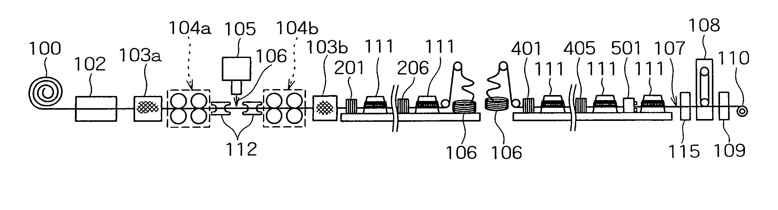
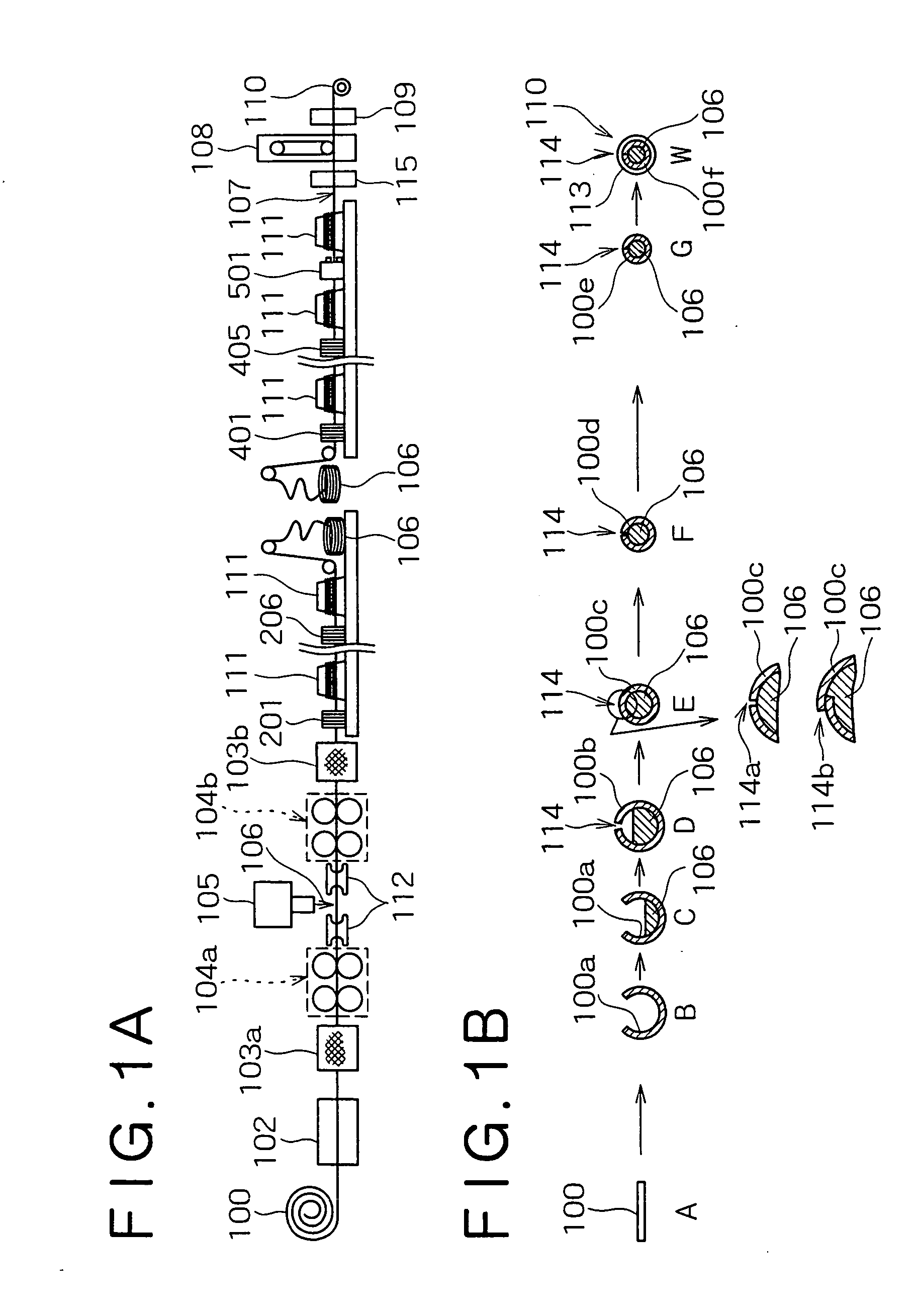
Below, examples of the present invention will be described. In the FCW manufacturing process shown in FIG. 1A, FCWs with a product diameter of 1.2-mm were manufactured using the respective band steels (hoops) made of mild steel sheets of the components shown in Table 1, using the respective fluxes of the components shown in Table 2, and using the respective lubricants shown in Table 3. In this step, as shown in Tables 4 and 5, the ratio t / W of the thickness t to the width W of the band steel was variously changed (within the ranges of the width of 12 to 14 mm and the thickness of 0.85 to 1.4 mm), and the secondary wire drawing conditions were changed as shown in Tables 4 and 5, thereby manufacturing FCWs. Incidentally, Table 4 shows the inventive examples and Table 5 shows comparative examples.

Herein, as the environment for the production of the FCWs, the conditions disadvantageous to the prevention of the moisture absorption of each wire flux during drawing were selected allowin...


PUM

PropertyMeasurementUnit
surface temperatureaaaaaaaaaa
diameteraaaaaaaaaa
lengthaaaaaaaaaa

Abstract

Disclosed herein is a manufacturing method, excellent in wire drawability, of a seamed flux-cored welding wire having both favorable feedability and low hydrogen content characteristic. The method for manufacturing a seamed flux-cored wire, comprises the steps of: drawing a tube-like formed wire including a flux filled therein using a lubricant; removing the lubricant from the drawn wire by a physical means; and coating a lubricant (coating an oil) for wire feeding on the wire surface. The respective steps are carried out in an in-line manner. In the wire drawing step, a wire drawing lubricant containing a sulfur-bearing high-pressure lubricant is used, and the overall wire drawing from the tube-like formed wire to a roughly product-diameter wire is carried out by means of a roller die.

Description

BACKGROUND OF THE INVENTION 1. Field of the Invention The present invention relates to a method for manufacturing a seamed flux-cored welding wire having both a favorable feedability and a low hydrogen content characteristic, the method being excellent in wire drawability. More particularly, it relates to a method for manufacturing a seamed flux-cored welding wire, suitable as an arc welding wire for fully automatic or semi-automatic welding to be used in welding of a mild steel, a high tensile strength steel, a heat-resistant steel, or the like. 2. Description of the Related Art Arc welding wires for fully automatic or semi-automatic welding include: a solid wire; and a flux cored wire (which is hereinafter simply referred to as a wire or a FCW) formed by filling a flux in a tube-like sheath steel strip (which is hereinafter also referred to as a hoop or a steel hoop). Out of these, FCWs include a type in which the hoop has a junction (which is hereinafter also referred to as a...

Claims


Application Information

Patent Timeline
Patent Type & Authority Applications(United States)
IPC IPC(8): B21C1/00B21C3/08B21C9/00B21C37/04B23K35/40
CPCB21C37/042Y10T29/49879B23K35/406B21C9/00B23K35/0266
Inventor MATSUGUCHI, AKIRAMIYAZAKI, KUNIAKIMASAIE, NORIO
Owner KOBE STEEL LTD
Why Eureka
Try Eureka