Liquid-liquid extraction apparatus and method

a technology of liquid-liquid extraction apparatus and method, which is applied in the direction of selective extraction, liquid displacement, working up pitch/asphalt/bitumen, etc., can solve the problems of reducing extraction efficiency and capacity, premature flooding, and increasing the complexity of the tray riser, so as to facilitate the restoration of the degraded perforation area. , the effect of proportionally slowing the loss rate of the tray perforation area

Active Publication Date: 2005-03-03
KELLOGG BROWN & ROOT INC
View PDF10 Cites 19 Cited by
  • Summary
  • Abstract
  • Description
  • Claims
  • Application Information

AI Technical Summary

Benefits of technology

[0012] We have discovered a liquid-liquid extraction method and apparatus achieving intimate contact between two liquid phases by passing a relatively heavier liquid phase descending through perforated sieve trays in a liquid-liquid extraction vessel. The sieve trays generate droplets of the heavy liquid and disperse the heavy liquid droplets into a continuous, relatively lighter ascending liquid phase. This

Problems solved by technology

Forte et al also features increasing tray riser complexity as vessel and tray diameter increase.
RDC's have evidenced operating problems such as backmixing or premature flooding, which can be caused by excessive shear of the rotating discs that can create too fine a dispersal of process liquids.
Both phenomena reduce extraction efficiency and capacity.
Lube oil deasphalting typically operates at elevated pressures that may equal or exceed supercritical pressure, and RDC's have been prone to seal leakage where disc drive shafts penetrate the extraction vessels.
In a number of RDC units seal leakage has been stopped or limited by welding the disc driv

Method used


Image

  • Liquid-liquid extraction apparatus and method
  • Liquid-liquid extraction apparatus and method
  • Liquid-liquid extraction apparatus and method

Examples


example 1

[0086] The present invention can be compared to alternative methods for liquid-liquid extraction in applications both as grassroots process designs and as retrofits to existing systems. For deasphalting of lubricating oil (lube oil) feedstocks, the prior art has used rotating disc contactors (RDC's) and packed-bed extraction vessels. Table 1 compares the present invention with RDC's using estimates of performance for selected operating parameters.

TABLE 1Performance Estimates for Solvent Deasphalting In PresentInvention Relative to Rotating Disc Contactor BaselineParameterPerformance of Present InventionLiquid Capacity20≧35% throughput increaseExtraction Efficiency2 times RDCProduct Yield0.5-5 volume percent increaseOperating CostLowerInvestment CostLower

[0087] RDC's consume energy to drive the disc contactors, which are not required in the present invention. Also, given an advantage in separation efficiency and capacity for the present invention, an RDC unit must consume extra pow...

example 2

[0089] To illustrate a range of retrofit options, Table 2 lists six cases of design dimensions for a lube oil solvent deasphalting application using the design of FIGS. 1-4, with reference to FIGS. 9-10 for simplified diagrams of sieve trays relating to dimensions in Table 2. The cases are for a potential retrofit of an existing RDC unit.

TABLE 2RDC RETROFIT CASESHeavy liquid flow = 93 m3 / hCommon Bases:Light liquid flow = 306 m3 / hParameterOption 1Option 2Option 3Option 4Option 5Option 6Vessel ID, m3.63.63.63.63.63.6Vessel Area, m210.1810.1810.1810.1810.1810.18Riser Area, m22.753.263.563.874.285.00Riser Area, % of273235384249VesselDeck Area, m27.436.926.626.315.905.18Perforation0.0420.0560.0840.1680.2480.112Area, m2Perforation689.5131925Diameter, mmPerforation1498112411831266874229Count Per Tray

[0090] A common basis in Table 2 is that each option at least meets the product specification of the RDC unit targeted for retrofit. In meeting the product specifications, the inventive optio...

example 3

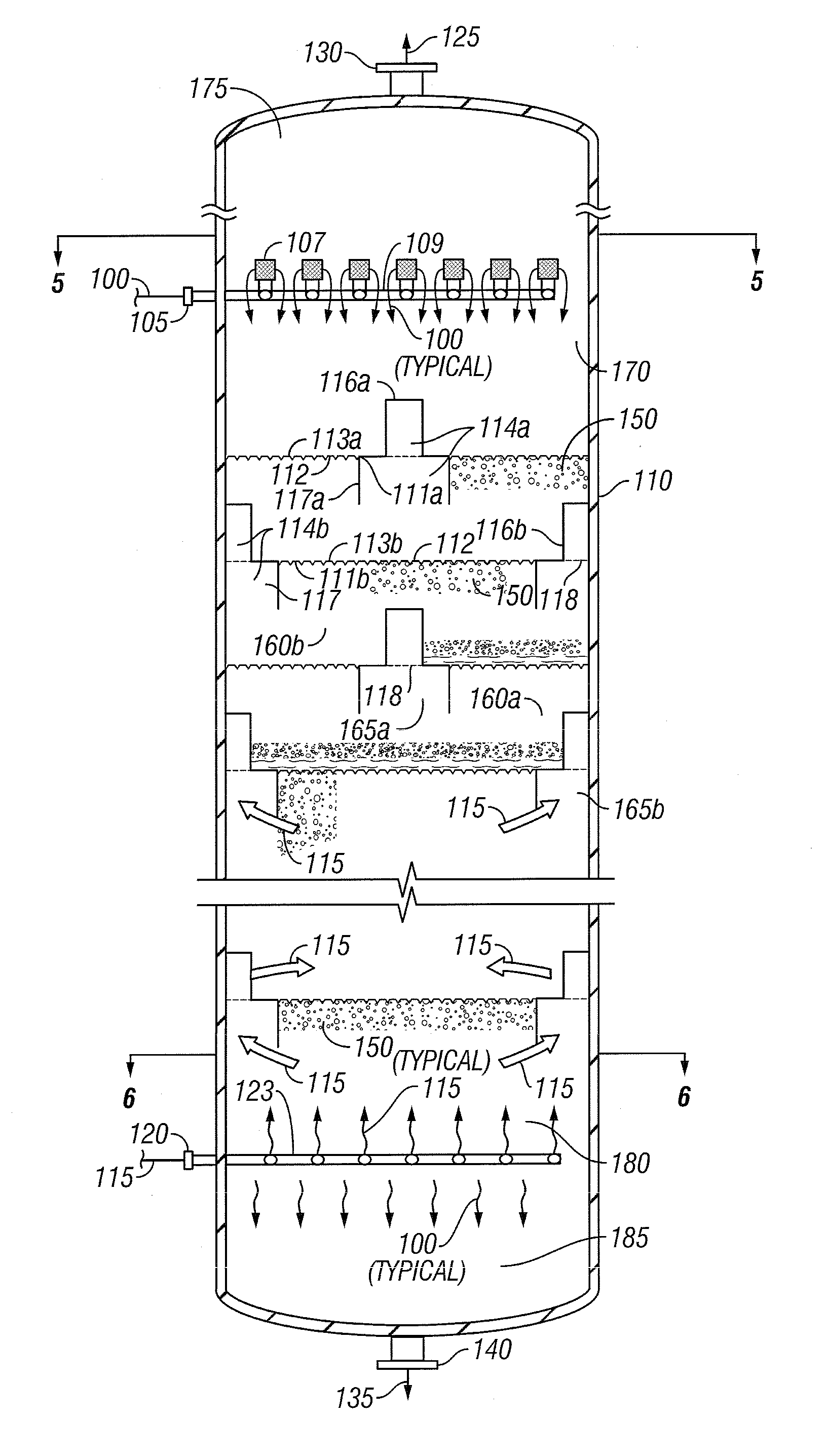
[0091] An extraction vessel conceptually similar to that shown in FIG. 1 is used in a liquid-liquid extraction process to remove asphaltene compounds from a lubricating oil raffinate feed stream, using propane as a solvent. Table 3 provides ranges of values for the compositions of the feed, extract, and raffinate product streams.

[0092] A lube oil feed stream is introduced as the heavy-phase liquid 100, entering the upper inlet 105 at a temperature of 100-250° F. The feed contains 50-90 volume percent asphaltene constituents. Simultaneously, propane is introduced at the lower inlet 120 at a flow rate of 5 to 15 times the volumetric flow of the feed and a temperature of 100-200° F. The extraction is operated with a temperature differential of 0-40° F. with respect to the oil feed temperature. The vessel 110 is operated at 2.75-4.8 MPa (400-700 psig). The raffinate product 135 is withdrawn at the bottom outlet 140 of the vessel 110 and contains a major fraction of the asphaltenes. An ...


PUM

PropertyMeasurementUnit
Lengthaaaaaaaaaa
Volumeaaaaaaaaaa
Volumeaaaaaaaaaa

Abstract

Method and apparatus for contacting two liquid phases for liquid-liquid extraction in a vertical extraction vessel. A relatively heavier liquid phase, descending the extraction vessel at a relatively low volumetric flow rate, is dispersed into a continuous phase comprising a relatively lighter liquid rising through the extraction vessel at a relatively high flow rate. Sieve trays are provided with adjustable active areas and overlapping manways for personnel access.

Description

BACKGROUND OF INVENTION [0001] The present invention relates to liquid-liquid extraction involving the dispersion of a relatively heavier liquid phase in a relatively lighter liquid phase, at elevated ratios of flow rates of light phase to heavy phase. The present invention also relates to mechanical improvements in liquid-liquid extraction equipment. [0002] In a typical form, liquid-liquid extraction processes perform mass transfer of target components from one liquid phase into a second liquid phase, typically to selectively recover valued components or eliminate undesirable components from one phase. The liquid phase containing the components to be extracted is called raffinate. The liquid phase that will extract the target components is called solvent, and when the solvent has completed the extraction, the solvent phase is called extract. [0003] In liquid-liquid extraction applications, two liquid phases are characterized by, among other properties, different relative solubiliti...

Claims


Application Information

Patent Timeline
IPC IPC(8): B01D11/04
CPCB01D11/043
Inventor NORTHRUP, ALDRICH HOLT JR.RESETARITS, MICHAEL ROBERTSANDFORD, NEIL ANTHONYTOKERUD, PAMELA JOGAGE, GARY WAYNECOLIC, VEADA
Owner KELLOGG BROWN & ROOT INC
Why Eureka
Try Eureka