
Method and apparatus for extruding a ceramic material

a ceramic material and extruder technology, applied in the field of ceramic material extrusion, can solve the problems of increasing the pressure of the extruder, affecting the production efficiency of the extruder, and observing the breakage of the web of the cellular extrudate (i.e., areas containing no ceramic material) in the extruded product, so as to reduce the wear of the filter screen

Active Publication Date: 2005-03-03
CORNING INC
View PDF6 Cites 30 Cited by
  • Summary
  • Abstract
  • Description
  • Claims
  • Application Information

AI Technical Summary

Benefits of technology

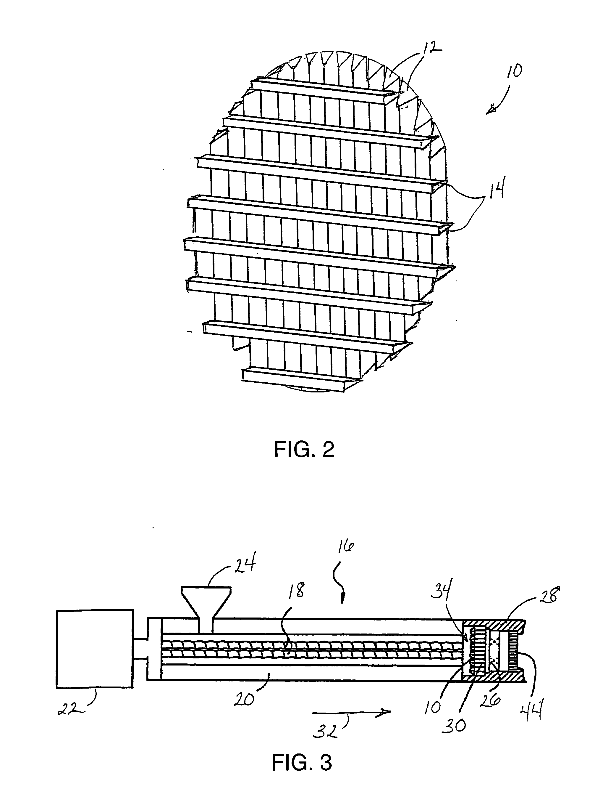
[0013] Preferably, a flat surface of the filter wires faces the extrusion direction of the batch material; more preferably an apex of the filter wires faces the extrusion direction of the batch material. By placing an apex of the filter wires in a direction facing the flow of batch material, low material wear and distortion of the filter screen can be achieved.
[0015] To reduce wear of the filter screen due to abrasion from the flowing batch material, the filter screen preferably has a wear resistant layer at the outer surface of the screen. The wear resistant layer may be applied by conventional methods such as thin film chemical vapor deposition or plasma vapor deposition, or by gas diffusion, such as with boron gas. Preferably, the filter screen has a wear resistant layer which includes a boride or a metal nitride, or the wear resistant layer may be a nickel-based coating.

Problems solved by technology

The production of honeycomb substrates with very thin webs is, however, very difficult when compared with substrates having a more conventional geometry.
It has been found that when conventional extrusion apparatus are used to produce ceramic honeycombs with web wall thicknesses of less than about 0.004 inches (0.01 cm), an unacceptably high number of breaks in the web of the cellular extrudate (i.e., areas containing no ceramic material) are observed in the extruded product.
However, the extremely thin cell walls, and the increasingly fine mesh requirements imposed upon the screen, result in increased pressure in the extruder.
This increased pressure may result in shutdown or damage to the extruder, as well as lead to poor geometry of the individual cell walls.
Another difficulty which stems from the filtering process is the generation of heat within the plasticized mixture, which causes a change in viscosity of the batch.
Such heat generation may be uneven, resulting in some portions of the batch fed to the extrusion die being relatively stiff and difficult to extrude, while other, softer portions of the batch will extrude more rapidly.
Unfortunately, attempts to increase production through the use of higher extruder operating speeds can result in an increased extruder pressure due to a large pressure differential across the filter screen.
The resistance to batch material flow is also responsible for increased, and potentially uneven, batch material core temperature.

Method used


Image

  • Method and apparatus for extruding a ceramic material
  • Method and apparatus for extruding a ceramic material
  • Method and apparatus for extruding a ceramic material

Examples


example

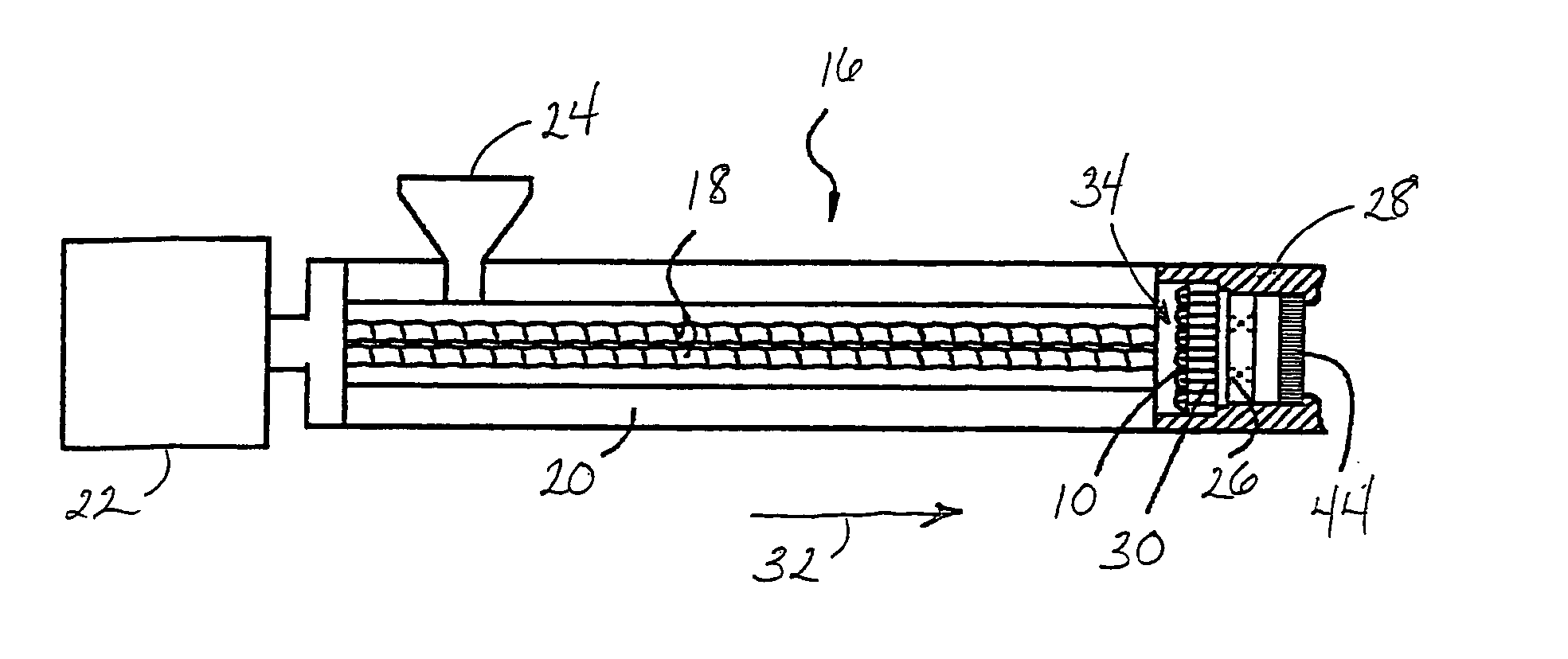
[0034] A twin screw extruder 16 was operated at a fixed commercial extrusion rate while extruding a commercial plasticized ceramic batch material into a honeycomb substrate used in the automotive industry. The batch filter consisted of a conventional woven wire filter screen. Process parameters, including the average differential pressure between the maximum pressure in the extruder barrel 20 upstream of the woven wire filter and the extruder pressure between the mixer plate 26 and the extrusion die 44 of the filter screen were measured and recorded. The average differential pressure for the conventional woven filter screen was 2042 psi. The filter screen 10 having wedge shaped filter wires 12 according to the present invention was then substituted for the conventional filter screen, after which the extruder 16 was again operated at the fixed commercial extrusion rate. The reduction in differential pressure by utilizing the filter screen 10 having wedge shaped wires over the convent...


PUM

PropertyMeasurementUnit
Flow rateaaaaaaaaaa
Wear resistanceaaaaaaaaaa
Electrical resistanceaaaaaaaaaa

Abstract

A method is provided for manufacturing a thin-walled honeycomb ceramic substrate by extruding a plasticized ceramic batch material through a filter screen having wedge shaped filter wires to remove foreign particulate and agglomerated batch material. The filter wires are supported by a set of support wires attached substantially perpendicular to the filter wires. The support wires are may also be advantageously wedge shaped. The filter screen of the present invention may have a wear resistant layer at the surface of the screen, typically a boride or a nitride. The wear resistant coating may also be a nickel-based coating.

Description

BACKGROUND OF THE INVENTION [0001] 1. Field of the Invention [0002] The present invention is directed to a method of extruding a ceramic material, and more specifically toward a method of filtering a plasticized ceramic batch material during the extrusion of a honeycomb ceramic substrate. [0003] 2. Technical Background [0004] A method for extruding structures of complex cross section from plasticized mixtures of inorganic powders and suitable binders is disclosed in U.S. Pat. No. 4,551,295 to Gardner et al. In this process a cordierite batch mixture consisting of inorganic clay, talc and alumina powders is combined with organic binders and water, and the resulting mixture is plasticized in the extruder. The plasticized batch mixture is then fed to a honeycomb extrusion die mounted on the end of the extruder. The resulting honeycomb substrates find significant use as liquid metal filter media, and as substrates for emission control devices, both in industrial applications and particu...

Claims


Application Information

Patent Timeline
IPC IPC(8): B28B3/22B29C48/11B29C48/32B29C48/395
CPCB28B3/206B28B3/22B28B3/26B29L2031/60B29C47/12B29C47/686B29C47/0028B29C48/11B29C48/693B29C48/40
Inventor SHALKEY, MARK A.
Owner CORNING INC
Learn More