Liquid cooling system and electronic apparatus using the same

a liquid cooling system and electronic equipment technology, applied in domestic cooling equipment, semiconductor/solid-state device details, ways, etc., can solve the problems of insufficient cooling, difficult to maintain the reliability of liquid cooling, and limited use of conventional technologies, so as to achieve the effect of maintaining corrosion resistan

Inactive Publication Date: 2005-03-03
HITACHI LTD
View PDF7 Cites 10 Cited by
  • Summary
  • Abstract
  • Description
  • Claims
  • Application Information

AI Technical Summary

Benefits of technology

[0017] An object, according to the present invention, is to provide a liquid cooling system enabling to maintain corrosion resistance for a long time period (for example, from 5 to 10 years), and also an electronic apparatus using the same therein.

Problems solved by technology

However, those conventional technologies are limited in the use thereof only in a filed of a large-scaled computer.
This is because the liquid cooling system comes to be large in the scale due to the fact that it needs a large number of parts for exclusive use of cooling, such as a pump, a piping system, a radiator, etc., and it is difficult to maintain the reliability in respect of applying the liquid into cooling thereof.
However, as was mentioned previously, an amount of heat-generation comes up every year, in particular, of the semiconductor elements, etc., which are used in the electronic apparatuses, such as, a personal computer, a home server, a projector, a media storage, etc., and for treating with it, but a compulsive cooling is not sufficient enough, with using the natural air cooling or a fan, or a cooling of using the heat pipe therein.
However, installation of the liquid cooling system into such the computer causes a new problem.
That is, due to the fact that only a small amount of the liquid is held within the liquid cooling system, and further that the operating temperature thereof is relatively high, etc., corrosion is promoted on the parts or elements in contact with the liquid, which are made of a metal material, such as, the heat-receiving jacket and the radiator, since the liquid is degraded in quality thereof even if the corrosive ion flow out in a very small amount thereof, in particular, from the parts or element of an organic material (i.e., the parts or element made of synthetic resin).
If causing water leakage due to the corrosion, it results into an important problem of stopping the function of that electronic apparatus; therefore, it is indispensable to make a treatment of measure of anti-corrosion on the parts or element, to be in contact with the cooling water.

Method used


Image

  • Liquid cooling system and electronic apparatus using the same
  • Liquid cooling system and electronic apparatus using the same
  • Liquid cooling system and electronic apparatus using the same

Examples


example 2

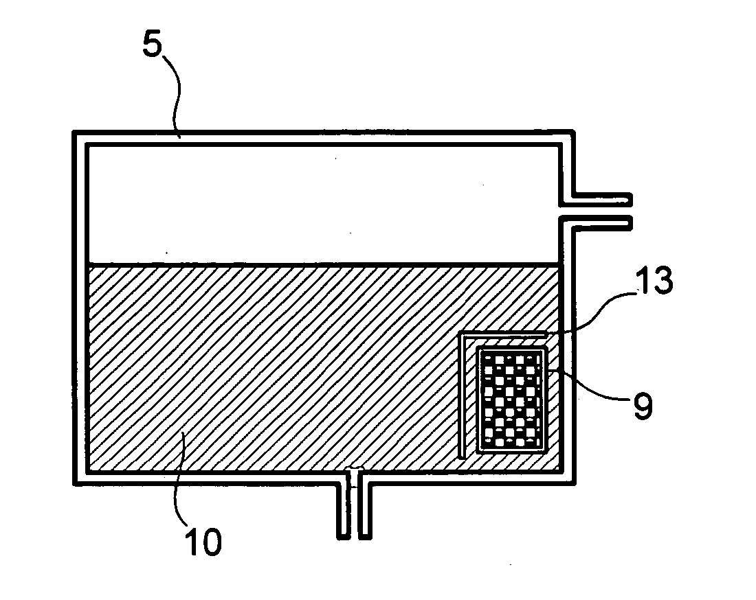
[0058]FIG. 5 is a view for showing the condition, in a case where the ion exchange bag is located at the predetermined position within the tank.

[0059] In this FIG. 5, surrounding the ion exchange bag is provided a partition plate 13.

[0060] With this, the ion exchange bag 9 will not comes up to the surface if a gaseous layer remains in an inside thereof, thereby enabling to adsorb the corrosive ions within the cooling liquid. Also, with provision of the partition plate 13 at the central portion of the tank 5, it is possible to hold the ion exchange bag 9 within the cooling liquid if the cooling system is used in any posture thereof. For this reason, the corrosive ions within the cooling liquid can pass through the water-permeable bag together with the cooling liquid, to be adsorbed by the ion exchange resin within the bag.

example 3

[0061]FIG. 6 is a view for showing other embodiment of the ion exchange bag therein.

[0062] In this FIG. 6, the water-permeable bag 12, having a hole 14 for use of fixing thereof, can be holed within the liquid, but without floating up when a gaseous layer is formed within the bag because of the low water-permeability thereof. For this reason, the corrosive ions within the cooling liquid can pass through the water-permeable bag together with the cooling liquid, to be adsorbed by the ion exchange resin within the bag.

example 4

[0063]FIG. 7 is a view for showing further other embodiment of the ion exchange bag therein.

[0064] In this FIG. 7, the water-permeable bag 12, having a weight 15 for use of prevention of floating, can be held within the liquid, but without floating up even if a gaseous layer is formed therein because of the low water-permeability thereof. In the case of using the anti-floating weight 15 thereon, the ion exchange bag can be held within the liquid when the cooling system is used in any posture thereof. For this reason, the corrosive ions within the cooling liquid can pass through the water-permeable bag together with the cooling liquid, to be adsorbed by the ion exchange resin within the bag. In a case where the tank is made of a metal, such as, iron, the weight 15 can be attached, easily if making it from a permanent magnet.

[0065] [Embodiment 5]

[0066]FIG. 8 is a view for showing an example of an ion exchange holder 16 therein.

[0067] In this FIG. 8, the ion exchange holder 16 has t...


PUM


Abstract

A liquid cooling system for use in an electronic apparatus, being super small-sized and thin in the shape and being suitable for cooling a heat-generation part, such as, a semiconductor element having large amount of heat generation, for example, with maintaining the corrosion resistance thereof for a long time period, comprises: a pump for supplying a cooling liquid; a heat-receiving jacket, being supplied with the cooling liquid, for receiving heat from an electronic parts; a radiator, being supplied with the cooling liquid passing through the heat-receiving jacket, for radiation heat; and flow passages for circulating the cooling liquid in a route passing through the radiator back to said pump, wherein an ion exchange bag, having an ion exchange resin and a bag enclosing it therein, is disposed in a part of the constituent parts of the liquid cooling system, and/or the ion exchange bag is exchangeable.

Description

BACKGROUND OF THE INVENTION [0001] The present invention relates to an electronic apparatus for cooling a semiconductor element therein, with using a liquid cooling system. [0002] The semiconductor element generates heat during the operation thereof, which is used in an electronic apparatus, such as a computer, etc. [0003] In particular, with the semiconductor in recent year, the heat-generation comes up much more, due to the demands on high processing speed and high capacity or performances thereof. In general, the semiconductor element looses the function of as the semiconductor element, remarkably, when exceeding over a predetermined level in temperature thereof, and therefore it is necessary to make compulsive cooling, in particular, on the semiconductor having a large amount of heat generation thereof. [0004] As a method for cooling down the semiconductor of the electronic apparatus, for example, there are already known methods of applying the heat conduction, applying an air c...

Claims


Application Information

Patent Timeline
Patent Type & Authority Applications(United States)
IPC IPC(8): G06F1/20F25D17/02H01L23/473H05K7/20
CPCG06F1/203G06F2200/201H01L23/473H01L2924/0002H01L2924/00E01F15/003E01F9/681E01F9/685E01F9/608
Inventor MINAMITANI, RINTAROMATSUSHITA, SHINJIOHASHI, SHIGEOKONDO, YOSHIHIRONAGANAWA, TAKASHISUZUKI, OSAMU
Owner HITACHI LTD
Why Eureka
Try Eureka