

Optical switch controller and movable body controller
- Summary
- Abstract
- Description
- Claims
- Application Information
AI Technical Summary
Benefits of technology
Problems solved by technology
Method used
Image

Examples
embodiment 1
[0069] (Embodiment 1)
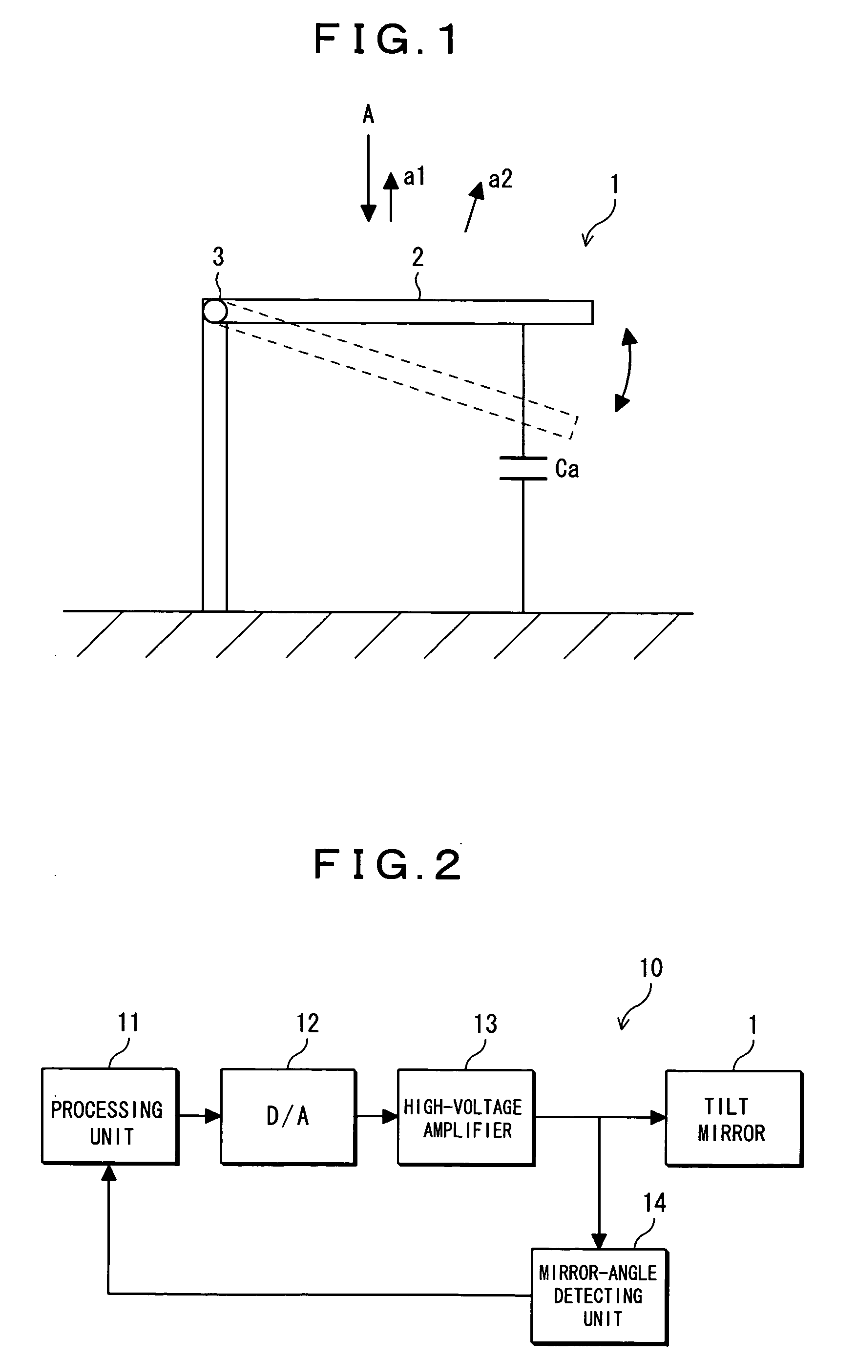
[0070] At first, embodiment 1 of an optical switch according to the present invention will be described. FIG. 1 shows the structure of an optical switch used in embodiment 1 of the present invention. This drawing shows a side view of a tilt mirror which is configured as an optical switch to which a MEMS technique is applied. In the tilt mirror 1 shown in the drawing, a mirror 2 a surface of which is a reflecting surface is able to swing with the axis 3 as the center. The angle of the mirror 2 in the horizontal state is 0°, and the position shown with dotted lines in the drawing is in the swinging direction of the mirror. By the swinging of the mirror 2, outgoing angles of incident light A are switched to given angles (a1 direction, a2 direction, or the like) to allow the incident light to output at the given angles. The mirror 2 swings only in the positive angle region shown in FIG. 26, where the rotational angle of the mirror 2 is proportional to (changes linea...
embodiment 2
[0079] (Embodiment 2)
[0080] Next, the optical switch of embodiment 2 of the present invention will be explained. The optical switch used in embodiment 2 has a structure as shown in FIG. 24 described above. In the tilt mirror 120 shown in the drawing, a mirror 2 a surface of which is a reflecting surface is able to swing with the center axis 3 as the center in the directions indicated by arrows shown in the drawing. The swinging of the mirror 2 switches the outgoing angle of incident light A to given angles (a1, a2, and a3 directions) in order to allow the incident light to output at the given angles.
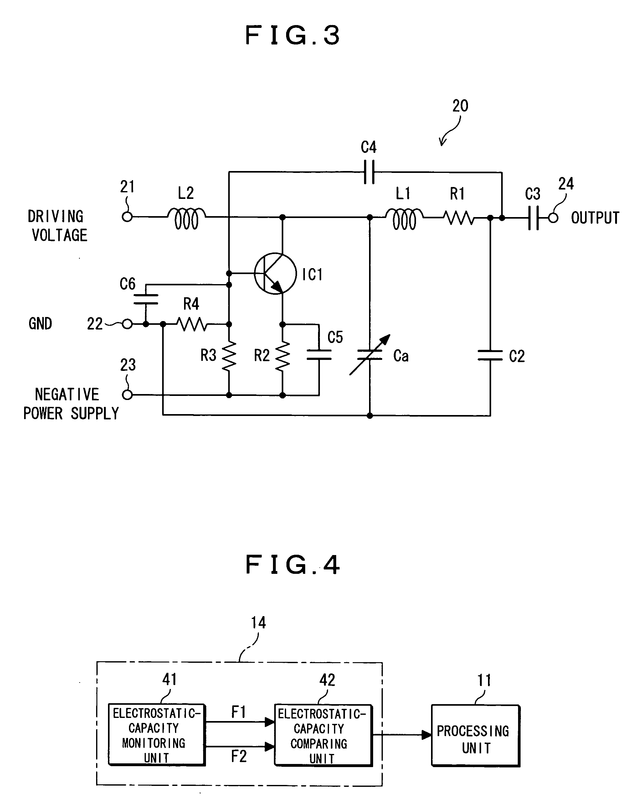
[0081] Embodiment 2 is different from embodiment 1 in configuration of the mirror-angle detecting unit 14. The configuration of a driving unit for the optical switch in embodiment 2 is nearly equal to that shown in FIG. 2, and explanation about it is omitted. FIG. 4 is a block diagram showing the internal configuration of the mirror-angle detecting unit in embodiment 2. The mirror-angle...
embodiment 3
[0094] (Embodiment 3)
[0095] Next, embodiment 3 of an optical switch according to the present invention will be described. In embodiment 3, another example of configuration of the mirror-angle detecting unit 14 described in embodiment 1 and embodiment 2 is explained. At first, FIG. 8 is a circuit diagram showing another example of configuration of the electrostatic capacity monitoring unit. The circuit configured as shown in FIG. 8 comprises a quartz resonator IC3, and can be used for the angle control of the tilt mirror 120 shown in FIG. 24. That is, this circuit can be provided instead of the LC oscillating circuits 51 and 52 shown in FIG. 5. Front stage and subsequent stage of the quartz resonator IC3, electrostatic capacities Ca and Cb of the tilt mirror 120 are provided in parallel respectively. When the angle of the mirror is changed, a signal having a resonance frequency corresponding to values of the electrostatic capacities is output from the output terminal 24 by the invers...
PUM
 Abstract
Description
Claims
Application Information