

Push-pull output driver
a push-pull output and driver technology, applied in the direction of logic circuits, pulse techniques, electronic switching, etc., can solve the problems of increasing the unacceptable of push-pull shoot-through noise, increasing the cost of corresponding charge dump via by-pass capacitors, and increasing the noise of push-pull shoot-through, so as to improve the performance of conventional push-pull drivers and improve the effect of non-overlap protection
- Summary
- Abstract
- Description
- Claims
- Application Information
AI Technical Summary
Benefits of technology
Problems solved by technology
Method used
Image

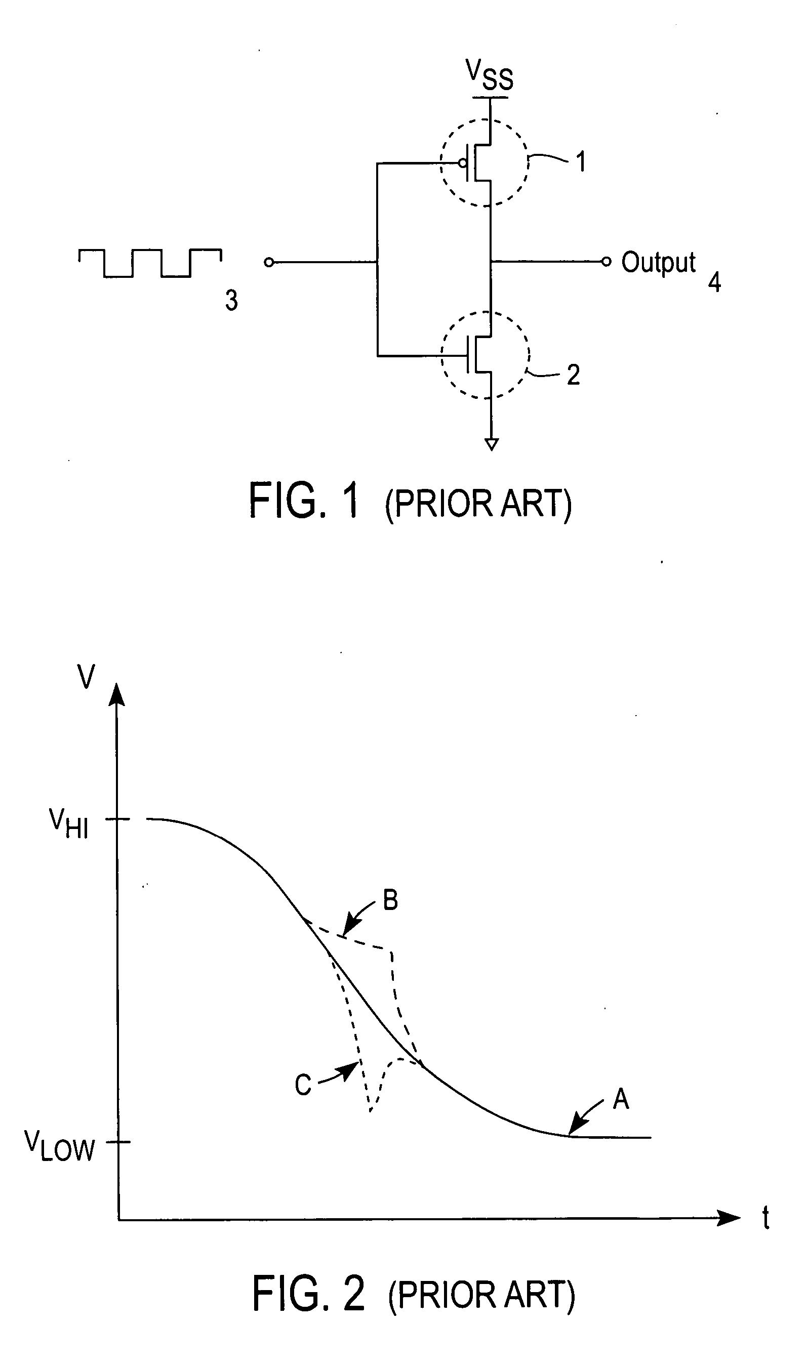
Examples
Embodiment Construction
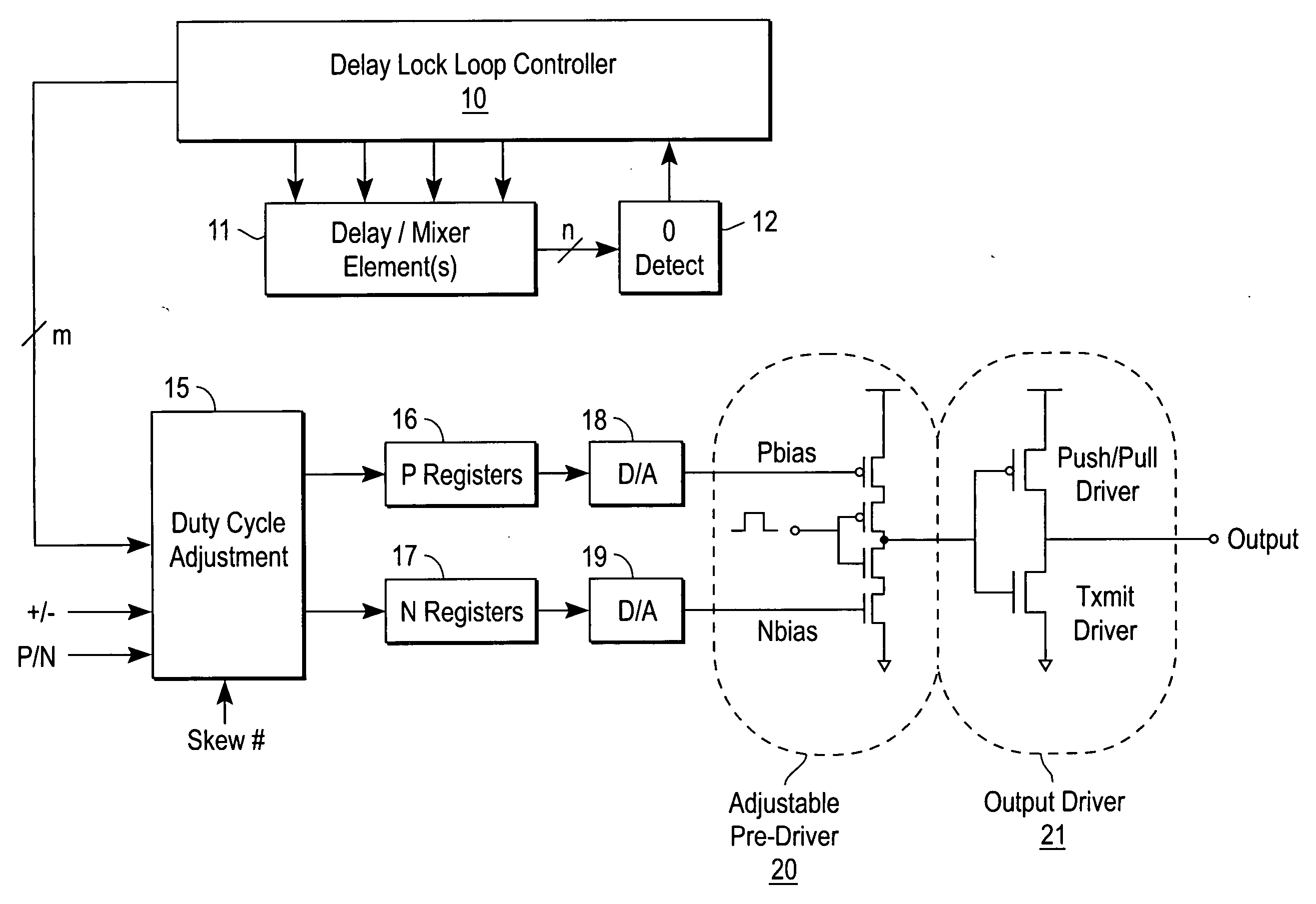
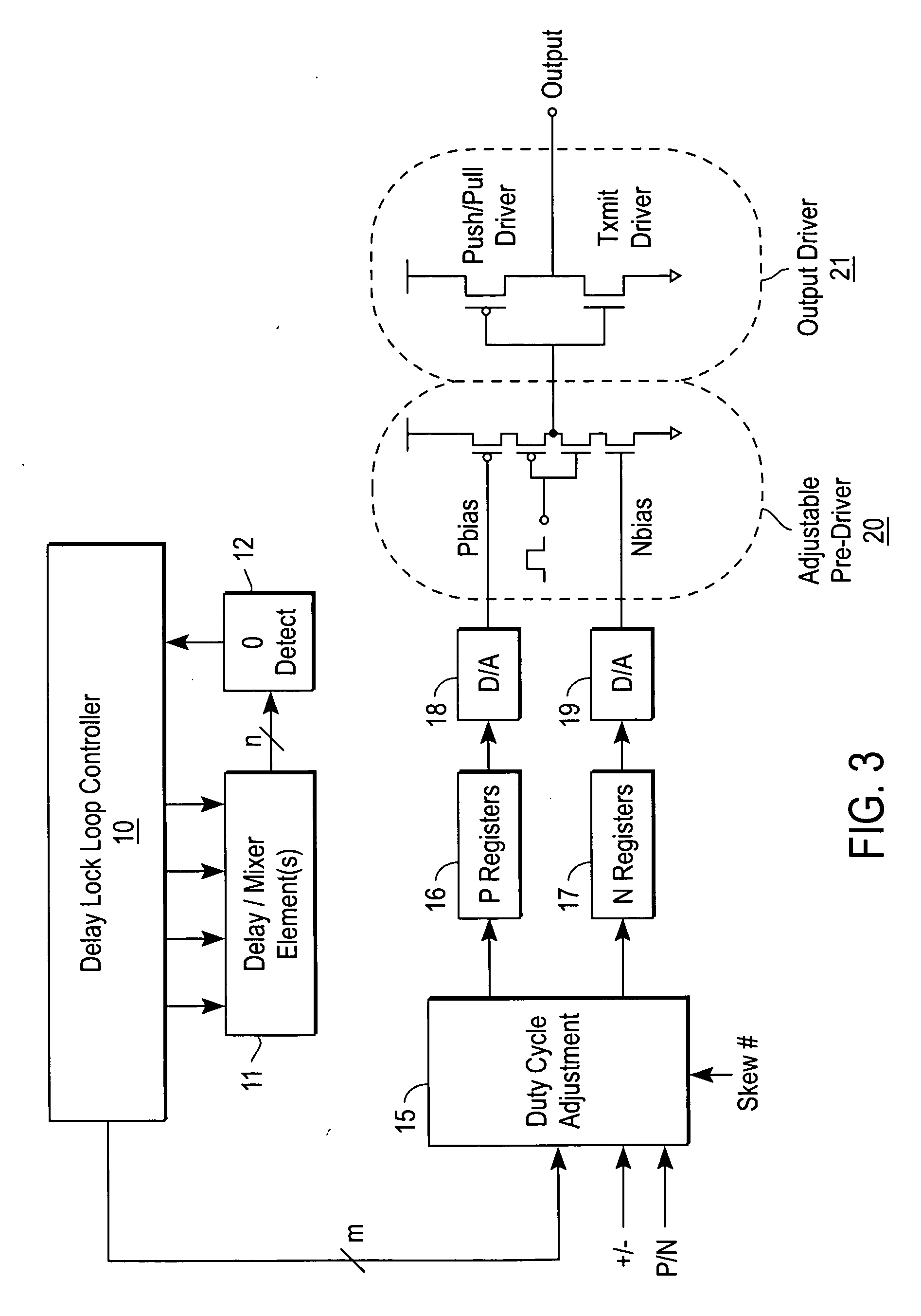
[0011] At a minimum, performance of the conventional push-pull driver would be greatly benefited from edge conditioning and / or improved non-overlap protection. Performance of the conventional push-pull driver would also be enhanced by providing slew rate control.
[0012] Edge conditioning prevents undershoot and overshoot at the terminal stages of the output waveform. The term “overlap” refers to the condition where both stages of the push-pull driver are ON (or conductive) and shoot-through occurs. Thus, non-overlap is a desired performance characteristic since shoot-through results in increased substrate (or backplane) noise and increased supply noise. Furthermore, shoot-through creates a requirement for larger by-pass capacitors. Increased by-pass capacitor size may result in a larger overall die size. Additionally, shoot-through results in increased power (and heat) dissipation within the semiconductor device.
[0013] The present invention provides greater non-overlap control, thu...
PUM
 Abstract
Description
Claims
Application Information