Filling structure

Inactive Publication Date: 2005-03-17
HONDA MOTOR CO LTD
View PDF2 Cites 28 Cited by
  • Summary
  • Abstract
  • Description
  • Claims
  • Application Information

AI Technical Summary

Benefits of technology

[0020] According to the second aspect of the invention, since the adhesive is adopted which has the property that the adhesive melts and expands by being heated for 10 to 30 minutes at a temperature of 140° C. to 190° C. and sets when cooled thereafter, the adhesive is allowed to melt, expand and set in the process of drying the coating film in a drying oven after the electro-deposition coating. As a result, there is provided an advantage that the process of the adhesive can be implemented by making use of the existing drying oven without providing an additional heating unit.
[0021] According to the third aspect of the invention, since the adhesive is adopted which has the property that the adhesive expands in volume by at least 10%, in a case where an adhesive is additionally provided in a filling

Problems solved by technology

Therefore, when the force is applied thereto, the surface tends to be damaged, and the joining force is decreased, whereby a gap might be formed between the frame portion 5 and the expanded aluminum 52 after a long time period of use.
Under such an environment or a corrosion environment where the water containing the snow-melting salt penetrates between the filling material and the hollow member, there is a possibility that corrosion might occur in the sheet-steel member where said corrosion propagates fro

Method used


Image

  • Filling structure
  • Filling structure
  • Filling structure

Examples


Embodiment Construction

[0027] Hereinafter, a best mode for carrying out the invention will be described based on the accompanying drawings.

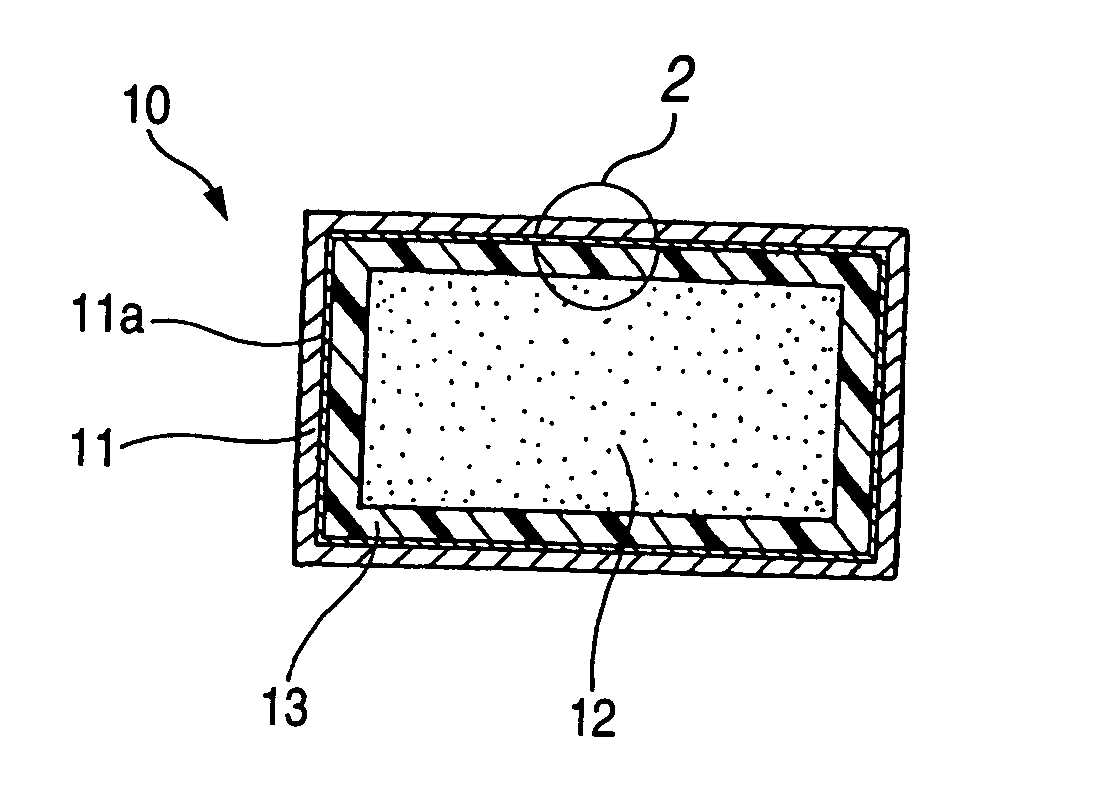
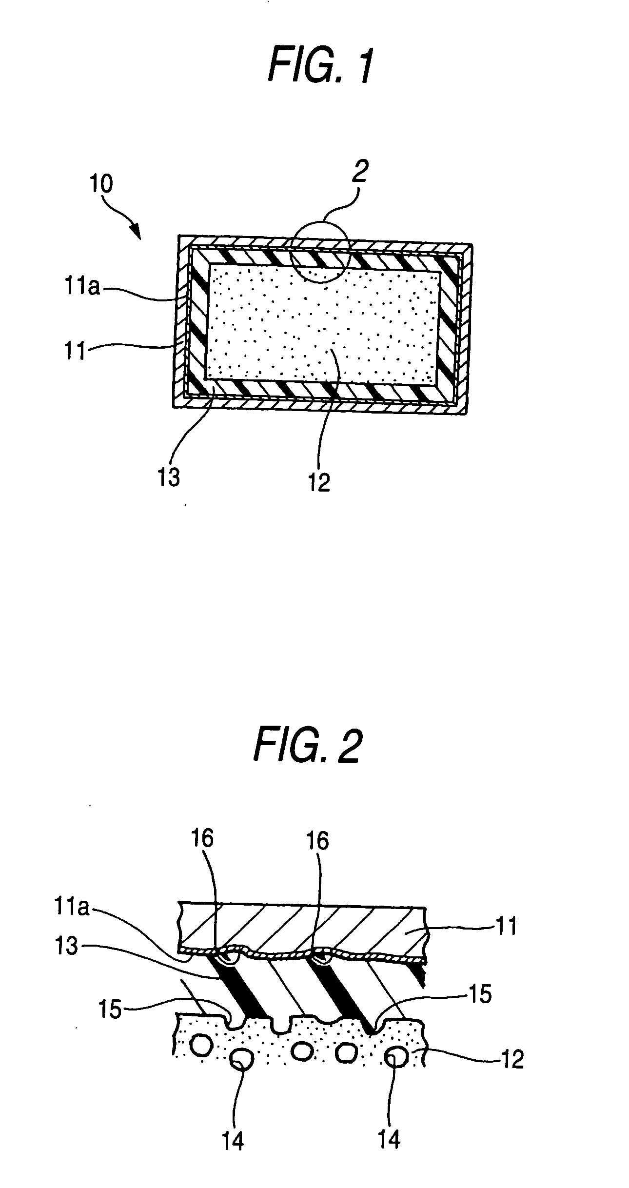
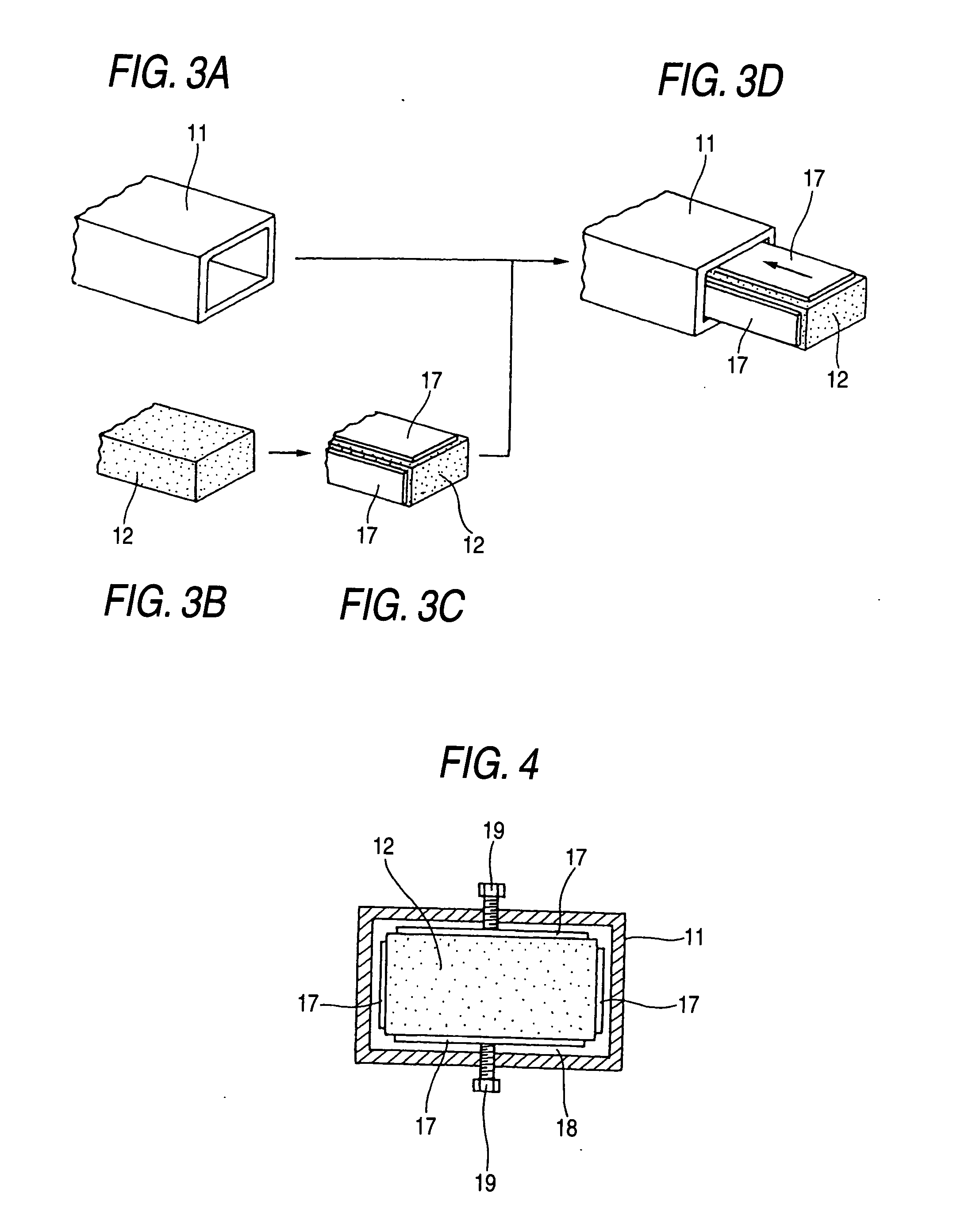
[0028]FIG. 1 is a cross-sectional view of a filling structure according to the invention, and a filling structure 10 is a structure in which a filling material 12 having a higher impact energy absorbing performance is inserted into the inner part of a hollow member 11 whose inner part surface is provided with a layer to which a corrosion protection treatment is applied, and the filling material 12 is fixed to the hollow member 11 with an adhesive layer 13 which results when the filling material 12 expands by being heated and sets thereafter.

[0029] The hollow member 11 is an extruded material produced by extruding a metallic ingot, a pressed product obtained by applying a plastic working on a sheet metal with a pressing machine, or a tubular member obtained in other manufacturing methods. An aluminum alloy, zinc alloy, iron alloy or other materials can be adopted as a...


PUM

PropertyMeasurementUnit
Temperatureaaaaaaaaaa
Fractionaaaaaaaaaa

Abstract

A filling structure 10 is a structure in which a filling material 12 having a higher impact energy absorbing performance is inserted into the inner part of a hollow member 11, and the filling material 12 so inserted is fixed to the hollow member 11 with an adhesive layer 13 resulting when the filling material 12 is heated to expand and is cooled to set thereafter.

Description

BACKGROUND OF THE INVENTION [0001] 1. Field of the Invention [0002] The present invention relates to a filling structure which is preferable for application to a vehicle body frame, in particular, to a bumper, a front side member and a pillar. [0003] 2. Description of the Related Art [0004] In recent years, there have been made attempts to improve the collision energy absorbing performance at the location of a certain vehicle body structural member by filling a material having a superior energy absorbing performance in the inner part of the structural member such as disclosed in JP-A-8-164869 [0005] The patent literature of JP-A-8-164869 discloses a technique described in its paragraph [0015] such as to state, “according to an embodiment shown in FIG. 1, an impact absorbing frame member 5 made up of the frame portion 51 constituted by an angular pipe stock and an expanded aluminum 52 filled in the inner part thereof is constructed by adding predetermined amounts of a thickener and a...

Claims


Application Information

Patent Timeline
IPC IPC(8): B60R19/18B62D25/04B60R19/22B62D21/15B62D29/00C08L63/00C08L75/04C09J5/08
CPCB60R19/18B60R2019/1813B62D29/002C08L63/00Y10T428/13C09J5/08C09J2463/00C09J2475/00C08L75/04
Inventor ISHIKAWA, RYOICHISHIBATA, KATSUHIROUEKI, MITSUHIKO
Owner HONDA MOTOR CO LTD
Why Eureka
Try Eureka