Composite tube for ethylene pyrolysis furnace and methods of manufacture and joining same

a technology of ethylene pyrolysis furnace and composite tubes, which is applied in the field of composite tubes, can solve the problems of high cost, high difficulty for material engineers, and limited range of optimal process parameters

Inactive Publication Date: 2005-03-17
HUNTINGTON ALLOYS CORP (US)
View PDF6 Cites 32 Cited by
  • Summary
  • Abstract
  • Description
  • Claims
  • Application Information

AI Technical Summary

Benefits of technology

[0009] The present invention provides a composite clad tube preferably consisting of an outer shell of a traditional wrought ethylene furnace tube alloy, such as INCOLOY® alloy 800HT, 803 or 890 and an inner layer of INCOLOY® alloy MA956. The composite clad tube is produced by co-extrusion of a fabricated billet utilizing INCOLOY® alloy MA956 powder in a canned type canister configuration within a trepanned (pierced) casting or forge billet of the shell alloy. The extruded composite shell is then preferably pilgered to a smooth-bore tube or, if desired, drawn to a finned or ribbed bore configuration, such as is described by England et al., in U.S. Pat. No. 5,016,460 dated May 21, 1991. During tube manufacture, the INCOLOY® alloy MA956 is not given a final grain-coarsening anneal (defined as at least one hour at 1200° C. or higher), in order to maintain the alloy in a fine grain, highly ductile condition. This

Problems solved by technology

The production of ethylene by steam cracking of alkanes, naphtha or vacuum gas oils, wherein the hydrocarbon feedstock passes within the inner bore of furnace tubing coils, presents a number of severe challenges to materials engineers.
This is especially true in the radiant sections of conventional furnaces, where the range of optimal process parameters is often limited by creep strength, carburization resist

Method used


Image

  • Composite tube for ethylene pyrolysis furnace and methods of manufacture and joining same
  • Composite tube for ethylene pyrolysis furnace and methods of manufacture and joining same
  • Composite tube for ethylene pyrolysis furnace and methods of manufacture and joining same

Examples


examples

[0029] Laboratory Examples

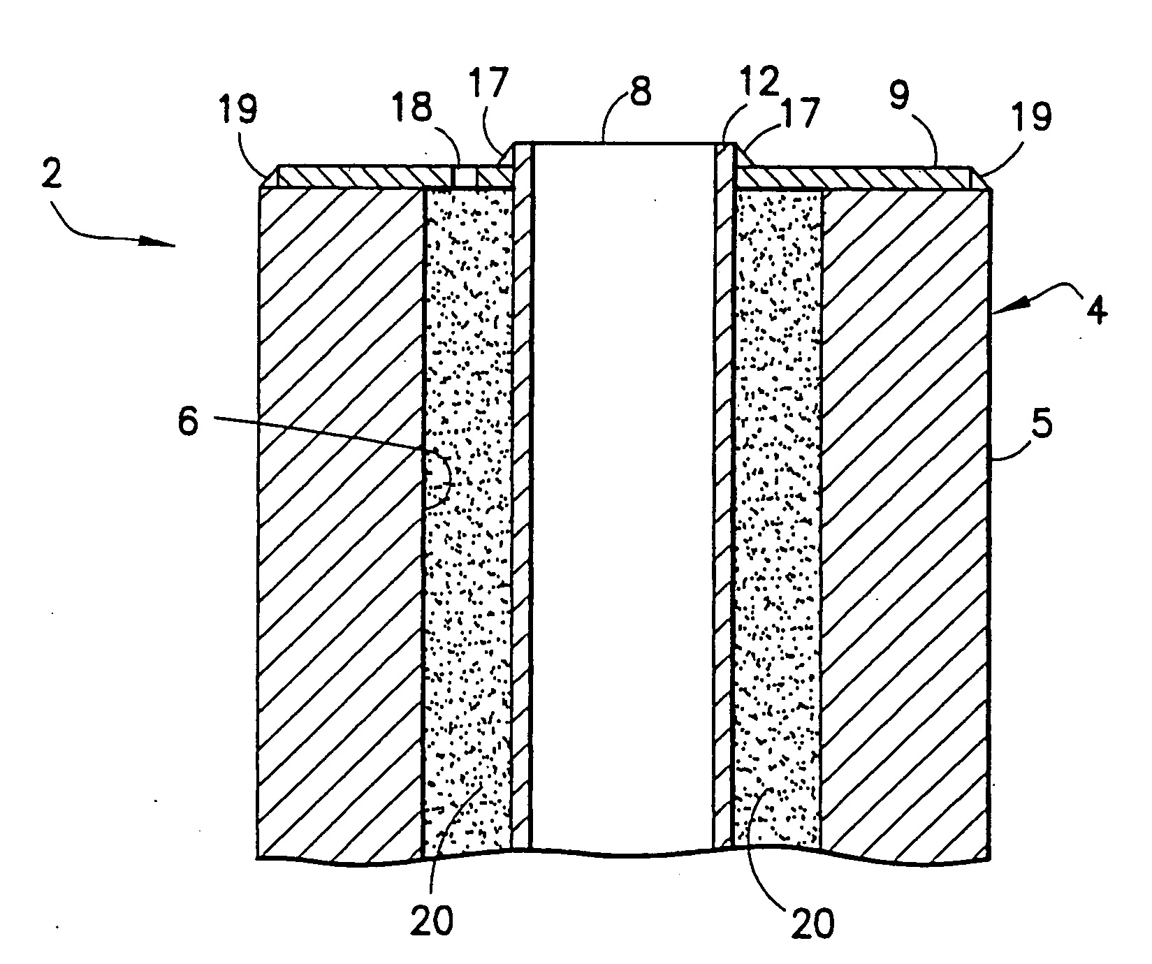
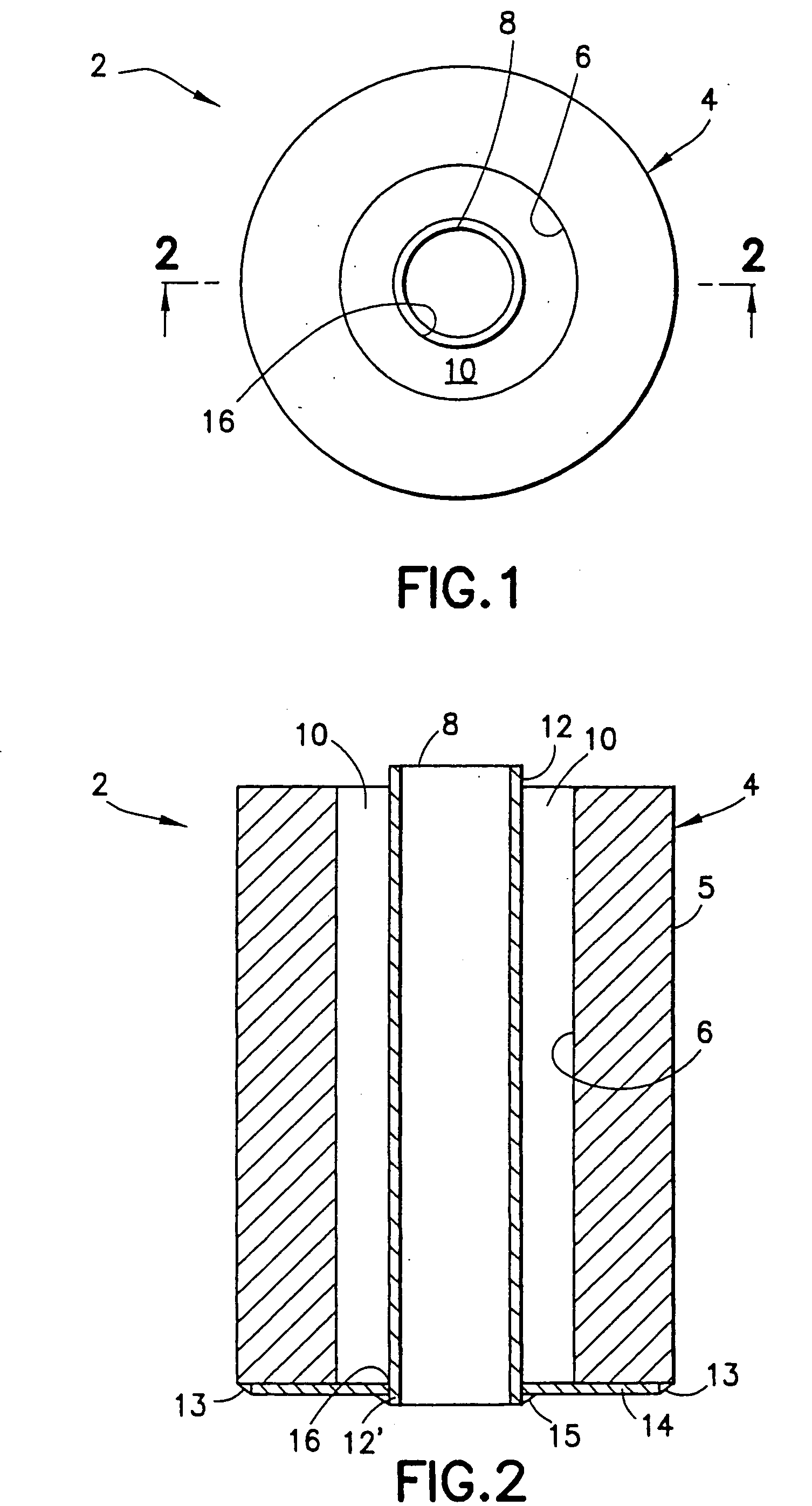
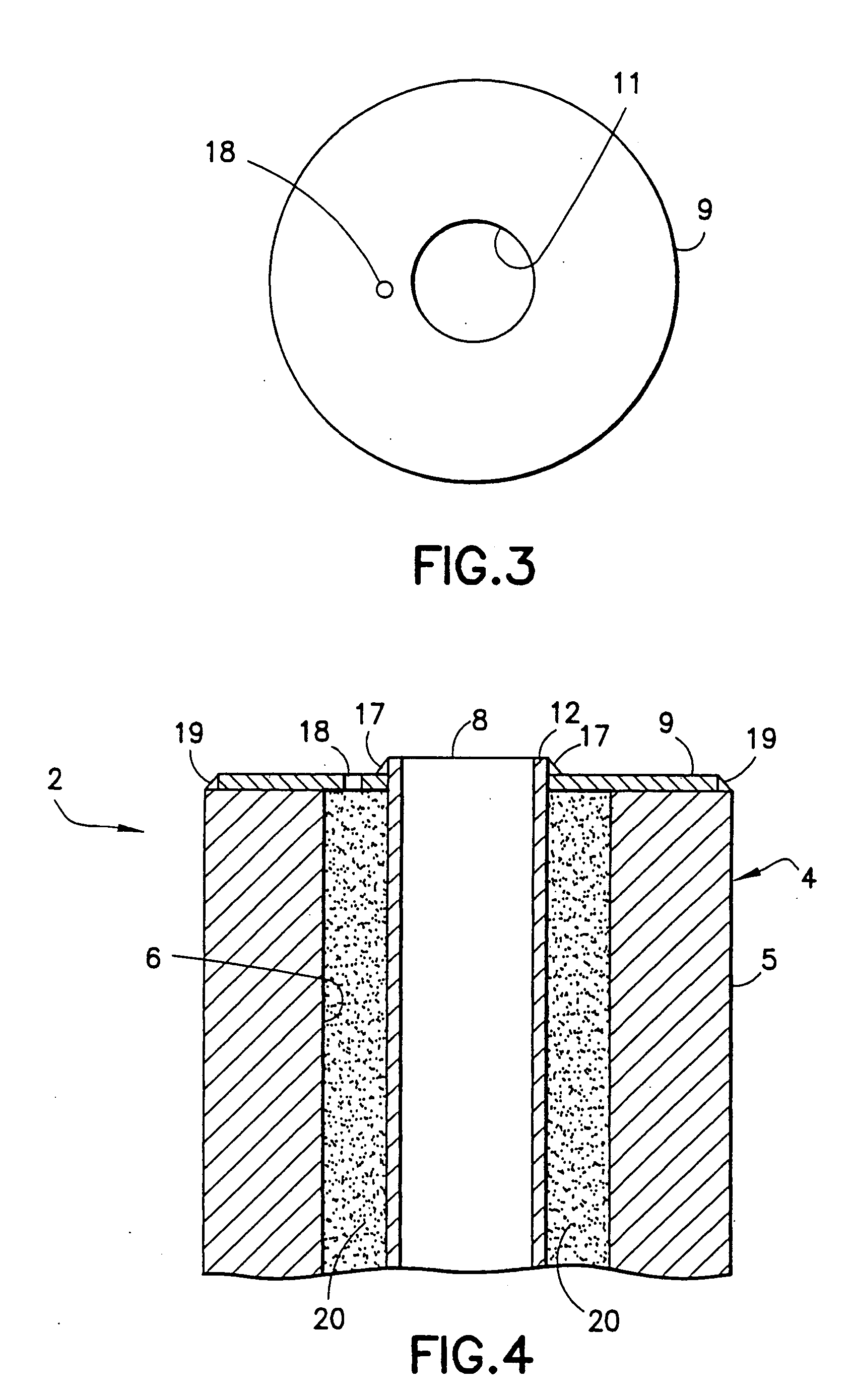
[0030] Four laboratory size composite tubes, designated 40 in FIGS. 7 and 8, were made to demonstrate the manufacturing process of the present invention and to confirm sound bond integrity at the interface 48 between the outer shell 42 comprising the conventional wrought alloy and the INCOLOY® alloy MA956 of the inner core 44. With reference to FIGS. 1-4, two of the outer shells 4 of INCOLOY® alloy 803, nominal composition, 25.6% Cr, 34.6% Fe, 0.5% Al, 0.5% Ti, 0.9% Mn, 0.7% Si, 0.2% Mo, 0.07% C, 0.001% B, balance Ni were prepared. This alloy was cast as about 115 mm diameter ingots and homogenized at 1177° C. for 24 hours. The shell ingots 4 were then machined to an outer diameter 5 of 88.65 mm and bored to an inner diameter 6 of 41.28 mm. The length of the machined outer shell 4 was approximately 300 mm. Using this outer shell 4, a ¼ inch thick bottom plate 14 with an inner diameter 16 of 25.53 mm and an outer diameter 5 of 85.73 mm was welded to the bott...


PUM

PropertyMeasurementUnit
Temperatureaaaaaaaaaa

Abstract

A process for making a composite tube uniquely suited for use in ethylene pyrolysis furnaces wherein the tube comprises an outer shell made from a wrought or cast Fe—Ni—Cr heat resistant alloy and an inner core made from INCOLOY® alloy MA956 powder. The outer shell and powder core are heated and simultaneously extruded to form a composite tube. The process is carried out at temperature, and time at temperature, preferably less than 1200° C. so as to prevent recrystalization of the very fine grain structure in the alloy MA956. This un-recrystalized fine grain structure permits pilgering and/or cold drawing of the extruded composite tube to final size. The composite tube provided by the present invention is uniquely suited for use in the petrochemical and chemical process industries, so as to increase the efficiency and productivity of their respective processes. The thin core layer of alloy MA956 provides high resistance to carburization and coke formation heretofore caused by the hydrocarbon feedstock flowing through the composite tube, while the outer shell of Fe—Ni—Cr heat resistant alloy provides overall strength and rigidity to the tube. The use of the outer shell in the composite tube also solves the joining problem heretofore encountered in joining alloy MA956. A root pass or passes using an alloy MA956 filler metal followed by overlay welding passes using a filler metal compatible with the heat resistant alloy, such as INCONEL alloy 617 or FM 25/35, joins the outer shells of adjoining composite tubes and, thus, solves the welding problem.

Description

BACKGROUND OF THE INVENTION [0001] 1. Field of the Invention [0002] The present invention relates to a composite tube suitable for use in the petrochemical and chemical process industries and, more particularly, suited for use in an ethylene pyrolysis furnace. The outer shell of the composite tube is made from high temperature heat-resistant Fe—Ni—Cr alloy and an inner core of a mechanically alloyed powder which is highly resistant to carburization and coke formation, wherein the shell and core are simultaneously extruded and then cold worked by pilgering or drawing to finished diameter. [0003] 2. Description of Related Art [0004] The production of ethylene by steam cracking of alkanes, naphtha or vacuum gas oils, wherein the hydrocarbon feedstock passes within the inner bore of furnace tubing coils, presents a number of severe challenges to materials engineers. This is especially true in the radiant sections of conventional furnaces, where the range of optimal process parameters is...

Claims


Application Information

Patent Timeline
IPC IPC(8): B21C23/22B21C37/06B21C37/15B22F3/16B22F7/08B23K9/00B23K35/30C10G9/20F16L9/02
CPCB21C23/22Y10T428/12965B21C37/06B21C37/154B22F3/162B22F7/08B22F2003/208B22F2009/041B22F2998/00B22F2998/10B23K9/0026B23K35/308B23K35/3086C10G9/203F16L9/02B21C33/004Y10T428/12937Y10T428/12979B22F9/04B22F3/20B22F3/16
Inventor SMITH, GAYLORD D.BAKER, BRIAN ALLENFAHRMANN, MICHAEL G.HARPER, MARK ANDREW
Owner HUNTINGTON ALLOYS CORP (US)
Why Eureka
Try Eureka