
Substrate for bio-microarray and bio-microarray

a bio-microarray and substrate technology, applied in the field of bio-microarrays, can solve the problems of reducing the analysis accuracy of substrates produced without optical processing, reducing the accuracy of substrate analysis based on the intensity of excitation light, etc., to increase the density of probes, suppress reflection, and increase detection accuracy

Inactive Publication Date: 2005-03-17
DAI NIPPON PRINTING CO LTD
View PDF13 Cites 11 Cited by
  • Summary
  • Abstract
  • Description
  • Claims
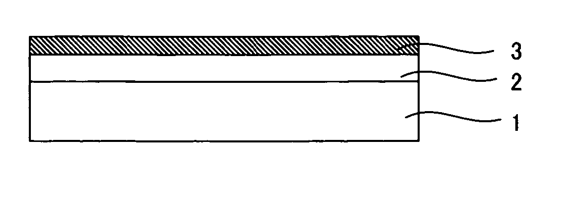
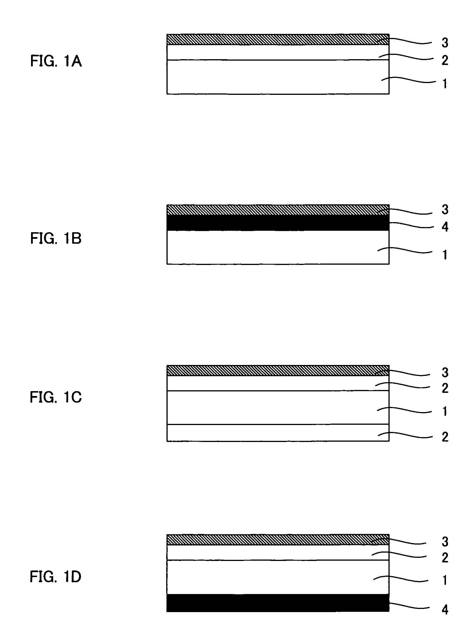
  • Application Information

AI Technical Summary

Benefits of technology

[0008] For the purpose of improving the accuracy of a variety of bio-microarray analyses, it is a main object of the invention to provide a bio-microarray capable of producing relatively high signal intensity from a fluorescent molecule and capable of having improved quantification performance and to provide a substrate for bio-microarray.
[0009] The invention provides a substrate for bio-microarray characterized by having a reflection-suppressing function. The inventive substrate for bio-microarray has the function of suppressing reflection and thus can increase the analysis accuracy through a relative increase in the signal intensity of the fluorescent molecule by the suppression of the reflection of the excitation light.
[0010] In the invention, at least one of an anti-reflection layer and a light-absorbing layer is preferably formed on the surface of the substrate so as to produce the reflection-suppressing function. The anti-reflection layer can suppress the reflection by increasing the transmittance of the excitation light, or the light-absorbing layer can suppress the reflection by absorbing the excitation light. The reflection-suppressing function can easily be given to the microarray substrate by the formation of the anti-reflection layer or the light-absorbing layer.

Problems solved by technology

In particular, the reflection of excitation light is a remarkable cause of the reduction in accuracy that can come from the substrate.
On the other hand, an increase in the detected signal intensity requires sufficient absorption of the excitation light into the label of the fluorescent molecule, and therefore, in some cases, suppression of the reflection of the excitation light can reduce the analysis accuracy depending on the intensity of the excitation light.
Specifically, however, substrates produced with no optical processing and substrates having the function of increasing the reflection are only commercially available now.
In some cases, such substrates cannot provide sufficient analytical accuracy, depending on the intensity of the excitation light.

Method used


Image

  • Substrate for bio-microarray and bio-microarray
  • Substrate for bio-microarray and bio-microarray
  • Substrate for bio-microarray and bio-microarray

Examples


example 1

[0102] Forming Anti-Reflection Layer on Substrate

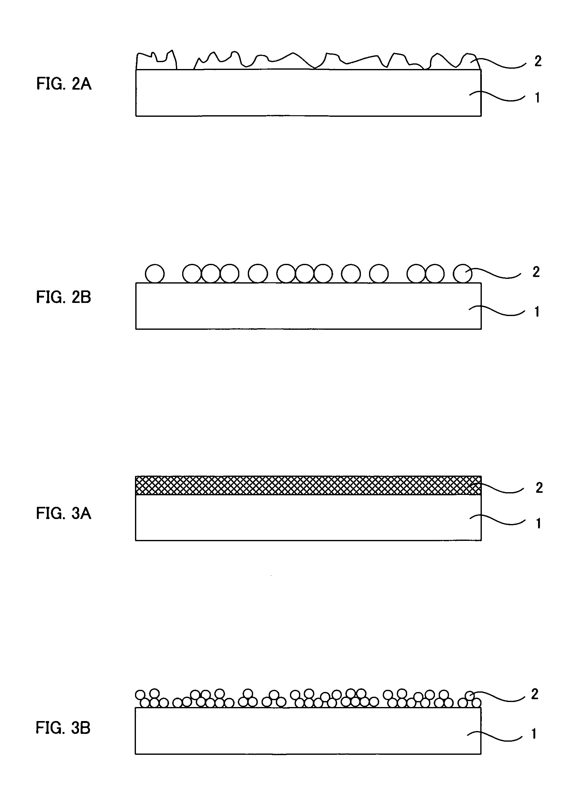
[0103] First, prepared were a solution of 0.4% polydiallyldimethylammonium chloride (PDDA with a molecular weight of 400,000 to 500,000 manufactured by Aldrich Chemical Company), a dispersion of silica particles (MP-1040 manufactured by Nissan Chemical Industries, Ltd.) and ion exchange water. A commercially available slide glass was washed and then immersed in the PDDA solution for two minutes so that PDDA was allowed to adsorb onto the slide glass. Washing with the ion exchange water was then performed for two minutes for the purpose of removing unnecessary PDDA. The PDDA-adsorbing slide glass was then immersed in MP-1040 for one minute for the purpose of forming an anti-reflection layer. After the silica particles were allowed to adsorb, washing with ion exchange water whose pH was adjusted to 10 was performed for four minutes. After the process, an anti-reflection layer comprising fine particles and having unevenness was formed o...

example 2

[0106] Forming Anti-Reflection Layer on Substrate

[0107] Prepared were a solution of 0.4% polyallyamine hydrochloride (PAH manufactured by Aldrich Chemical Company), a solution of 0.4% polyacrylic acid (PAA manufactured by Aldrich Chemical Company), and ion exchange water. The PAH solution and the PAA solution were prepared so as to have a pH of 7.8 to 8.5 and a pH of 3.5, respectively. A commercially available slide glass was washed and then subjected to 10 cycles of PAH / PAA alternate adsorption (10 cycles of PAH adsorption and 10 cycles of PAA adsorption) so that a layer-by-layer self-assembled film was prepared. The film was then treated with acid so as to have a porous structure / uneven structure for providing an anti-reflection performance. Heat treatment was then performed to crosslink PAH and PAA by amide bond so that the anti-reflection structure was fixed. A series of these processes were according to Hiller et al., Nature Materials, Vol. 1, page 59, 2002.

[0108] (Forming Im...

example 3

[0110] Forming Anti-Reflection Layer on Substrate

[0111] The process of Example 1 was used.

[0112] (Forming Immobilization Layer on the Substrate Having Anti-Reflection Layer)

[0113] Chemical vapor deposition using 3-aminopropyltriethoxysilane (manufactured by Across Chemical Co.) was performed to form an amino group-containing layer on the surfaces of the silica particles used in the anti-reflection layer. A microarray substrate was prepared by a series of these processes.


PUM

PropertyMeasurementUnit
particle diameteraaaaaaaaaa
depthaaaaaaaaaa

Abstract

For the purpose of improving the accuracy of a variety analyses using a bio-microarray, it is a main object of the invention to provide a bio-microarray capable of producing relatively high signal intensity from a fluorescent molecule and capable of having improved quantification performance and to provide a substrate for bio-microarray. In order to achieve the object, the invention provides a substrate for bio-microarray characterized by having a reflection-suppressing function.

Description

BACKGROUND OF THE INVENTION [0001] 1. Field of the Invention [0002] The invention relates to a bio-microarray having probe biomolecules such as DNA, peptide, protein, polysaccharide, cell, and tissue, which are arranged in an array, and also relates to a substrate for bio-microarray. [0003] 2. Description of the Related Art [0004] In recent years, the target of development of bio-microarrays (also referred to as biochips) has been expanded and thus includes not only DNA microarrays, which have been used in genome analysis, but also microarrays that load any other biomolecules such as peptide, protein, polysaccharide, cell, and tissue. [0005] The bio-microarray analysis method generally includes the processes of introducing a fluorescent molecule as a label into a sample and analyzing light emission from the fluorescent molecule, because such a process is appreciated as having a high sensitivity and a variety of available labels. Examples of the analytical apparatus according to this...

Claims


Application Information

Patent Timeline
Patent Type & Authority Applications(United States)
IPC IPC(8): G01N33/53B01J19/00C12M1/00C12N15/09C40B70/00G01N33/543G01N37/00
CPCB01J19/0046B01J2219/00527B01J2219/0054B01J2219/00596C40B70/00B01J2219/00612B01J2219/00637B01J2219/00641B01J2219/00659B01J2219/00605
Inventor HATTORI, HIDESHI
Owner DAI NIPPON PRINTING CO LTD
Learn More