The world is experiencing an unacceptable growth in
traffic congestion and attention is increasingly turning to smart highway systems to solve the problem.
Such systems are expensive to install, difficult and expensive to maintain and will thus only be used on major highways, if at all.
Although there will be some safety benefit from such systems, it will be limited to the highways which have the
system and perhaps to only a limited number of lanes.
Simple neural networks are probably not sufficient for this purpose and
neural fuzzy, modular neural networks or combination neural networks are probably required.
Naturally, since
radar cannot accurately determine this area, it has to be assumed by the
system.
Thus, true collision avoidance cannot be obtained without an accurate knowledge of the road geometry.
This can lead to significant errors.
Lemelson also does not make use of accurate map
database and thus it is unable to distinguish cases where two cars are on separate lanes but on an apparent collision course.
Thus, the Lemelson system is unable to provide the accuracy and reliability required by the Road to Zero Fatalities™ system described herein.
While these sensors, meters, elements, systems and controls have served limited specific purposes, the prior art has disadvantageously failed to integrate them in a comprehensive fashion to provide a complete dynamic
route guidance, dynamic vehicular control, and safety improvement system.”
However, displacement wheel sensors are plagued by tire slippage, tire wear and are relatively inaccurate requiring recalibration of the current position.
Compasses are inexpensive, but suffer from drifting particularly when driving on a straight road for extended periods.
Compasses can sense turns, and the system may then be automatically recalibrated to the current position based upon sensing a turn and correlating that turn to the nearest turn on a digitized map, but such recalibration, is still prone to errors during excessive drifts.
Moreover, digitized map systems with the
compass and wheel sensor positioning methods operate in two dimensions on a three dimensional road
terrain injecting further errors between the digitized map position and the current vehicular position due to a failure to sense the distance traveled in the vertical dimension.”
However, the GPS reception is not used for automatic accurate recalibration of current vehicular positioning, even though C-MIGITS and like devices have been used for
GPS positioning, inertial sensing and epoch time monitoring, which can provide accurate continuous positioning.”
“These Intelligent Vehicle Highway Systems use the
compass and wheel sensors for vehicular positioning for
route guidance, but do not use accurate GPS and inertial
route navigation and guidance and do not use inertial measuring units for dynamic vehicular control.
Even though dynamic electronic vehicular control, for example, anti-lock braking, anti-skid steering, and electronic control suspension have been contemplated by others, these systems do not appear to functionally integrate these dynamic controls with an accurate inertial route
guidance system having an inertial measuring unit well suited for
dynamic motion sensing.
While two-way
RF communication is possible, the flow of necessary information between the vehicles and central system appears to be exceedingly lopsided.
The Intelligent Vehicular Highway Systems disadvantageously suggest a required two-way RF
radio data system.
To the extent that any system is bi-directional in operation tends to disadvantageously require additional frequency bandwidth capacity and system complexity.”
However, in order to reach its full potential for navigation, GPS needs to be augmented both to improve accuracy and to reduce the time needed to inform a vehicle driver of a malfunction of a GPS
satellite, the so-called integrity problem.
In most radio systems, bandwidth is a finite limitation which dictates how much data can be sent in a given time period.
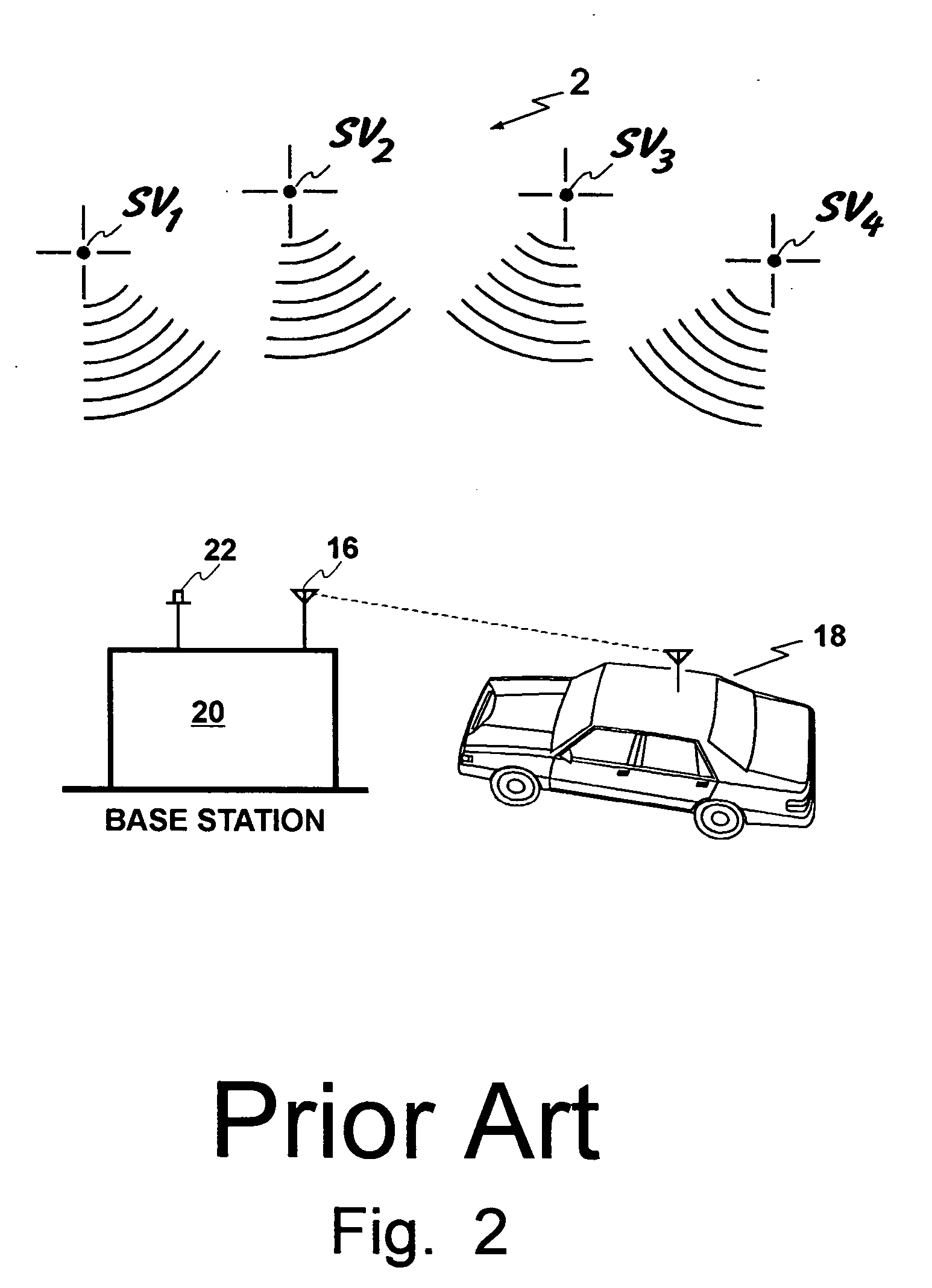
Every
base station automatically corrects for atmospheric errors at it's location; but the user is not at any of those locations, so the corrections are not optimized for the user—and, OMNISTAR has no information as to each individual's location.
If it is totally ignored, errors of up to ten meters can result.
However, when the standard deviation of approximately 0.5 meter is considered, it is evident that this WAAS system is insufficient by itself and will have to be augmented by other systems to improve the accuracy at least at this time.
This system provides accuracy that is not as good as GPS.
Errors are more often common when receivers are close together (less than 100 km).
Unfortunately, the respective error sources mentioned above rapidly decorrelate as the distances between the reference
station and the vehicle increases.
This system will not meet all of FAA's requirements.
In countries with a limited number of airports, LAAS is not very expensive while the costs of building a WAAS to get Category 1 type accuracy is very expensive.
For the purposes of the RtZF™ system, both the WAAS and LAAS would be useful but probably insufficient unless the information is used in a different mathematical system such as used by the OmniSTAR™ WADGPS system.
Unlike an
airplane, there are many places where it might not be possible to receive LAAS and WAAS information or even more importantly the
GPS signals themselves with sufficient accuracy and reliability.
This system still suffers from the availability of accurate signals at the vehicle regardless of its location on the roadway and the location of surrounding vehicles and objects.
This, of course, is the RMS error.
Thus, this real time
wide area differential GPS system is not sufficiently accurate for the purposes of some embodiments of this invention.
In practice, multipath affects, usually from nearby surfaces, limit the accuracy achievable to around 5 millimeters.
In this case, most of the other GPS error sources are common.
The only major problem, which needs to be solved to carry out high precision kinematic GPS, is the
integer ambiguity problem.
However, it is unclear as to whether the second position system is actually more accurate than the GPS system.
This combined system, however, cannot be used for sub-meter positioning of an automobile.
This procedure does not give sub-meter accuracy.
“The range is called a “
pseudorange” because the
receiver clock may not be precisely synchronized to GPS time and because propagation through the
atmosphere introduces delays into the navigation
signal propagation times. These result, respectively, in a
clock bias (error) and an atmospheric bias (error).
However, precise (e.g., atomic) clocks are expensive and are, therefore, not suitable for all applications.”
Therefore, the P-mode sequences are held in secrecy and are not made publicly available.
This forces most GPS users to rely solely on the data provided via the C / A mode of modulation (which results in a less accurate
positioning system)
“In addition to the
clock error and atmospheric error, other errors which affect GPS position computations include
receiver noise,
signal reflections, shading, and
satellite path shifting (e.g.,
satellite wobble).
These errors result in computation of incorrect pseudoranges and incorrect satellite positions.
Incorrect pseudoranges and incorrect satellite positions, in turn, lead to a reduction in the precision of the position estimates computed by a
vehicle positioning system.”
The computational resolution of the
integer ambiguity has traditionally been an intensive arithmetic problem for the computers used to implement GPS receivers.
Very often such highly accurate GPS receivers have required long periods of motionlessness to produce a first and subsequent position fix.”
Search techniques often require significant computation time and are vulnerable to erroneous solutions when only a few satellites are visible.
If carried to an extreme, a
phased array of antennas results whereby the integers are completely unambiguous and searching is unnecessary.
The pseudo-random code can be used as a coarse indicator of differential range, although it is very susceptible to multipath problems.
However
dual frequency receivers are expensive because they are more complicated.
But such motion may not always be present when it is needed.”
However, it mentions that this will be limited to controlled access roads such as interstate highways.
This patent does not give sub-meter accuracy.
Much information is lost in this system, however, due to the lack of knowledge of the vehicle's velocity.
Aside from that, it suffers from all the disadvantages of
radar systems as described here.
In particular, it is not capable of giving accurate three-dimensional measurements of an object on the roadway.
As a result, it is not possible to identify the objects in the
field of view.
Also, no attempt has been made to determine whether the object is located on the roadway or not.
On the other hand, if scanning this array at 100 feet, it would take 200 nanoseconds for the light to travel to the obstacle and back.
According to the Federal Highway Administration Intelligent Transportation Systems (ITS Field Operational Test), dynamic route guidance systems have not been successful.
This is unnecessary and the communications can be general since the amount of information that is unique to one vehicle is small.
However, the author (unnecessarily) complicates matters by using
push technology which isn't absolutely necessary and with the belief that
the Internet connection to a particular vehicle to allow all vehicles to communicate, would have to be stopped which, of course, is not the case.
DSRC could be used for inter-vehicle communications, however, its range according to the ITS proposal to the Federal Government would be limited to about 90 meters although there have been recent proposals to extend this to about 1000 meters.
Also, there may be a problem with interference from
toll collection systems, etc.
This would not be sufficient for the RtZF™ system.
Fifty meters amounts to about one second, which would be insufficient time for the passing vehicle to complete the passing and return to the safe lane.
This, however, may interfere with other uses of DSRC such as automatic
toll taking, etc., thus DSRC may not be the optimum communication system for communication between vehicles.
“Automotive suppliers cannot sell infrastructure-dependent systems to their customers until the very large majority of the infrastructure is suitable equipped.”
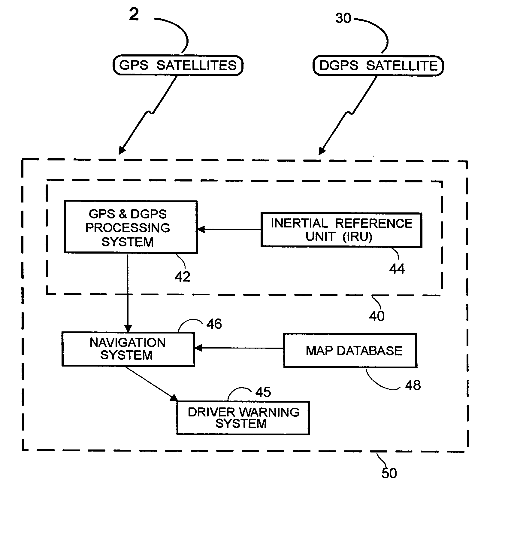
Additionally, no prior art system is believed to have successfully used the GPS
navigational system, or an augmented DGPS to locate a vehicle on a roadway with sufficient accuracy that that information can be used to prevent the equipped vehicle from leaving the roadway or striking another similarly equipped vehicle.
Prior art systems in addition to being poor at locating potential hazards on the roadway, have not been able to ascertain whether they are in fact on the roadway or off on the side, whether they are threatening vehicles, static signs, overpasses etc.
In fact, no credible attempt to date has been made to identify or categorize objects which may
impact the subject vehicle.
“Out-of-position” as used for an occupant will generally mean that the occupant, either the driver or a passenger, is sufficiently close to an occupant protection apparatus (
airbag) prior to deployment that he or she is likely to be more seriously injured by the deployment event itself than by the accident.
It may also mean that the occupant is not positioned appropriately in order to attain the beneficial, restraining effects of the deployment of the
airbag.

