Surface plasmon optic devices and radiating surface plasmon sources for photolithography

Inactive Publication Date: 2005-03-24
MAX BORN INST FUT NICHTLINEARE OPTIK & KURZZEITSPEKTROSKOPIE +1
View PDF13 Cites 26 Cited by
  • Summary
  • Abstract
  • Description
  • Claims
  • Application Information

AI Technical Summary

Benefits of technology

[0016] A surface plasmon splitter using coherence of the surface plasmon according to the present invention comprises a metal diffraction grating having a periodic aperture array or a cylindrical array located at the propagation direction of the surface plasmon. The surface plasmon dispersed in each aperture or cylinder of the metal diffraction grating can be divided and propagated only in a specific direction that satisfies a constructive interference condition. Using the coherence of the surface plasmon, the surface plasmon splitter of the present invention can effectively divide the surface plasmon.
[0017] Another surface plasmon splitter using a tunneling effect of the surface plasmon comprises separated two metal interfaces respectively having a specific angle with respect to the propagation direction of the surface plasmon, and a dielectric body filled therebetween. At this time, a distance between the two metal films and a rate of the surface plasmon divided by a dielectric constant of the dielectric body can be controlled, and also the propagation direction of the surface plasmon reflected by an angle of the metal interface with respect to the propagation direction can be controlled. Therefore, the surface plasmon splitter of the present invention can facilely control a separate rate of the surface plasmon and the propagation direction.
[0018] A surface plasmon mirror of the present invention comprises a metal interface having a specific angle with respect to the propagation direction of the surface plasmon, and a dielectric body outside the metal interface. This uses a characteristic that the surface plasmon can be propagated only along the metal surface. A reflection rate is decided by a dielectric constant of the dielectric body and the propagat

Problems solved by technology

However, it is a fact that understanding of a

Method used


Image

  • Surface plasmon optic devices and radiating surface plasmon sources for photolithography
  • Surface plasmon optic devices and radiating surface plasmon sources for photolithography
  • Surface plasmon optic devices and radiating surface plasmon sources for photolithography

Examples


Embodiment Construction

[0055] The present invention will now be described in further detail by examples.

[0056] Referring to FIG. 1 to FIG. 5c, it will be described of generation, propagation and interference characteristics of surface plasmon, which are found by experiments of the inventors.

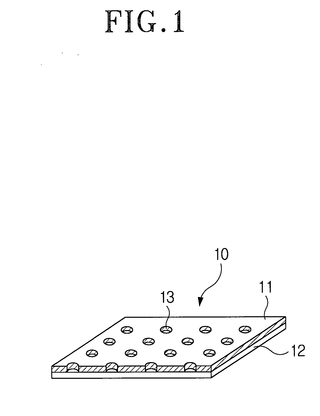
[0057]FIG. 1 is a perspective view of a surface plasmon generating apparatus having a periodic aperture array of a grating structure according to the present invention. The surface plasmon generating apparatus 10 comprises a dielectric substrate 12 having an upper surface and a lower surface, an optically thick metal film 11 formed on the upper surface of the dielectric substrate 12, and an array of a periodic grating structure of a two dimensional nanometer-sized aperture 13 formed in the metal film 11. The metal film 11 is made of a metal such as gold and silver, and deposited in a thickness of 300 nm on the dielectric substrate 12. The array of the aperture 13 is formed using a dry etching technique after e-beam l...


PUM


Abstract

Disclosed is a surface plasmon optic device that has a periodic array of apertures in a dielectric substrate and a metal film formed on the dielectric substrate and emits light from metal-air interface. The surface plasmon optic device includes a surface plasmon generating apparatus, a surface plasmon detecting apparatus, a surface plasmon controlling apparatus, an etching apparatus, etc. if a metal diffraction grating is disposed on the metal film having a well-defined interface, propagation of the surface plasmon can be efficiently reflected, divided and controlled. Further, radiating surface plasmon having a half period of a lattice constant formed at air-metal (1, 0) can be preserved at a distance of at least a few micron.

Description

TECHNICAL FIELD [0001] The present invention relates to a device for generating and adjusting surface plasmon using periodically arranged apertures formed in a metal film and a photolithography device using the same. BACKGROUND ART [0002] Generally, a thick metal film has a non-transmission property with respect to incident light. Even though apertures are formed through the metal film, if a size of each aperture is much smaller than a wavelength of the incident light, a light amount transmitted through the metal film is remarkably reduced. However, it is well known that, if the apertures are periodically arranged in the metal film and an arranged period of the apertures has a size of the wavelength of the incident light, the light is efficiently transmitted through the metal film, though each aperture has a smaller size than the wave length of the incident light. Furthermore, as a result of recent research, a spectral position and intensity of such transmission resonance phenomenon...

Claims


Application Information

Patent Timeline
IPC IPC(8): G02B6/12G02B6/10G02F1/01G03F7/20
CPCG02B6/10G03F7/70375G02F2203/10G02F1/01
Inventor KIM, DAI-SIKHOHNG, SUNG-CHULLIENAU, CHRISTOPHMALYARCHUCK, VICTORPARK, JONG-WANYOON, YEO-CHANRYU, HAN-YOULYOO, KYEONG-HWA
Owner MAX BORN INST FUT NICHTLINEARE OPTIK & KURZZEITSPEKTROSKOPIE
Why Eureka
Try Eureka