Continuous and non-continuous flow bioreactor

Inactive Publication Date: 2005-03-24
CAPLIPER LIFE SCI INC
View PDF7 Cites 51 Cited by
  • Summary
  • Abstract
  • Description
  • Claims
  • Application Information

AI Technical Summary

Benefits of technology

The invention comprises microscale bio-reactors and related methods. The bioreactors are configured, e.g., for continuous flow amplification of nucleic acids, including RNA and / or DNA amplification. The use of a continuous flow format provides an advantage to previous methods, in that the concentration of reactants (and products) can be maintained at desired levels, providing for a more controllable and optimizable reaction. For example, because the concentration of reactants can be held at an optimal point by a system, the system can produce optimal amounts of product. Further, because products such as RNA amplicons are continuously removed in certain continuous flow embodiments, amplification reactions do not display product inhibition (inhibition of the reaction by product formation).
One feature of the invention is the optimization of reaction parameters, e.g., for performing an mRNA amplification in a microscale system. Such reaction parameters can be any that are relevant to performing the assay, e.g., a rate of flow in the chamber, a temperature in the chamber, a concentration of one or more of the RNA amplification reagents in the chamber, inhibiting or enhancing DNA transcription in the amplification chamber, a channel size leading into or out of the chamber, a size of the chamber, a bead diameter of a bead bound to one or more additional RNA amplification reagent (e.g., a template), total porosity of a bead bed bound to one or more additional RNA amplification reagent, a percent of fluid that diffuses in and out of a bead bed bound to one or more additional RNA amplification reagent as the fluid flows through and along the bead bed, residence time of (and distance traveled by) the reaction substrates or products through the bead bed, direction of flow of one or more reactants or products through a bead bed, and / or the like. In one example embodiment, reactants are flowed through a bead bed (which can be, e.g., in a channel, chamber or well) in a direction transverse (orthogonal) to flow of products out of the bead bed. For example, reactants can be flowed into the bead bed along a long dimension of the bead bed (reactants generally can generally flow relatively freely through a bead bed), while products are flowed across a short dimension of the bead bed (products can be more resistant to flow through the bead bed, and yields can be improved by configuring the flow path of products for reduced flow). Alternately, reagents and products can both be flowed through the short dimension of the bead bed, minimizing trapping of both reagents and products by the bead bed. In either embodiment, the beads themselves are optionally flowed in a direction transverse (orthogonal) to the flow of the reactants and / or products.

Problems solved by technology

Further, because products such as RNA amplicons are continuously removed in certain continuous flow embodiments, amplification reactions do not display product inhibition (inhibition of the reaction by product formation).

Method used


Image

  • Continuous and non-continuous flow bioreactor
  • Continuous and non-continuous flow bioreactor
  • Continuous and non-continuous flow bioreactor

Examples


Embodiment Construction

The following examples are intended to be illustrative, but not limiting. One of skill will immediately recognize a variety of non-critical parameters that can be altered.

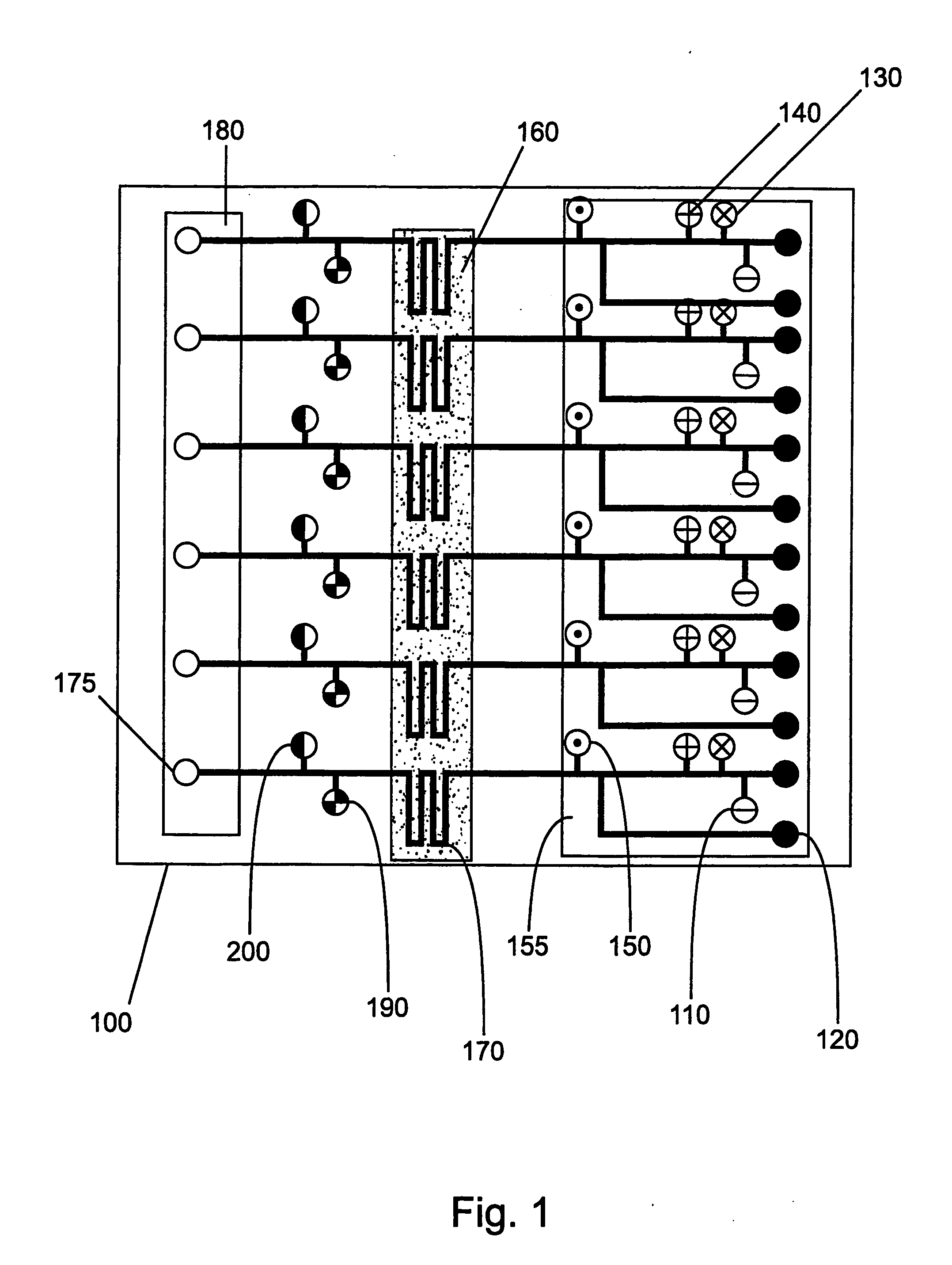
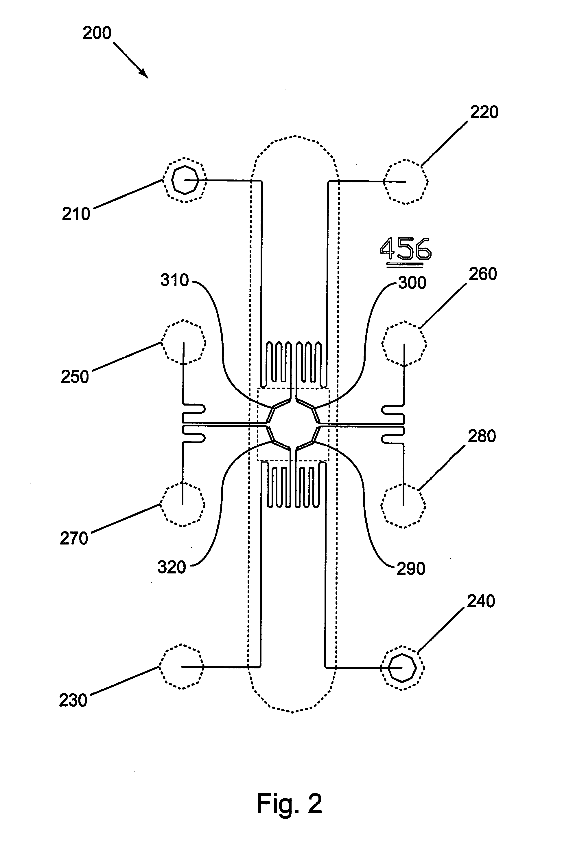
Continuous Flow Bioreactors

Continuous flow bioreactors of this example are designed to operate in a continuous flow, temperature controlled mode. The bioreactors of this example are microscale devices in which reagents are delivered in a continuous flow format for on-device, temperature controlled enzymatic reactions. The reactions are conducted in microscale chambers (in this case channels) of the microscale devices. This is in contrast to prior art RNA amplification reactions, which do not, ordinarily, utilize continuous reagent replacement to keep a reaction going indefinitely. In addition, the reactor of this example overcomes products inhibition effects (e.g., in the case of RNA amplification, sense suppression effects occur as product is produced). This inhibition is overcome with the reactors of this ex...


PUM

PropertyMeasurementUnit
Timeaaaaaaaaaa
Flow rateaaaaaaaaaa
Sizeaaaaaaaaaa

Abstract

Methods and systems for performing continuous amplification of RNA and other nucleic acids are provided. Expression profiling using the continuous flow RNA amplification systems are also provided.

Description

BACKGROUND OF THE INVENTION RNA production is central to all of biology. As has been understood for roughly half a century, messenger RNA (mRNA) is translated in the cell into proteins, which carry out most cellular operations. For example, in eukaryotes, mRNA is typically produced from nuclear RNA (nRNA), which is an RNA copy of a region of genomic DNA, by various splicing mechanisms. RNAs in general are typically encoded by genomic DNAs (gDNAs), with either mRNA or nRNA being produced by transcription of such DNA. This paradigm of DNA to RNA to protein is sometimes referred to as the “central paradigm” of molecular biology. Despite a few variations, such as those practiced by various RNA viruses (which can, e.g., have an RNA genome that is reverse transcribed into DNA and then replicated by transcription of the DNA back into RNA), this paradigm describes a basic way in which organisms encode cellular functions. See also, Alberts et al. (2002) Molecular Biology of the Cell, 4th Ed...

Claims


Application Information

Patent Timeline
IPC IPC(8): B01J19/00B01L3/00B01L7/00C12N15/11C12P19/34C12Q1/68
CPCB01L3/5027B01L7/52B01L2400/0415B01L2400/049C12Q1/6844C12Q1/6865C12Q1/686C12Q2565/629
Inventor DETTLOFF, ROGERKIRBY, CELESTEGENTALEN, ERIKROSOFF, MONICA
Owner CAPLIPER LIFE SCI INC
Why Eureka
Try Eureka