

Method and apparatus for assay of electrochemical properties
a technology of electrochemical properties and assay equipment, applied in the field of electrochemical properties assay equipment, can solve the problems of inaccurate measurement of signal and estimate of analyte concentration, added uncertainty and error to the measured signal, and increased uncertainty and error
- Summary
- Abstract
- Description
- Claims
- Application Information
AI Technical Summary
Benefits of technology
Problems solved by technology
Method used
Image

Examples
example 1
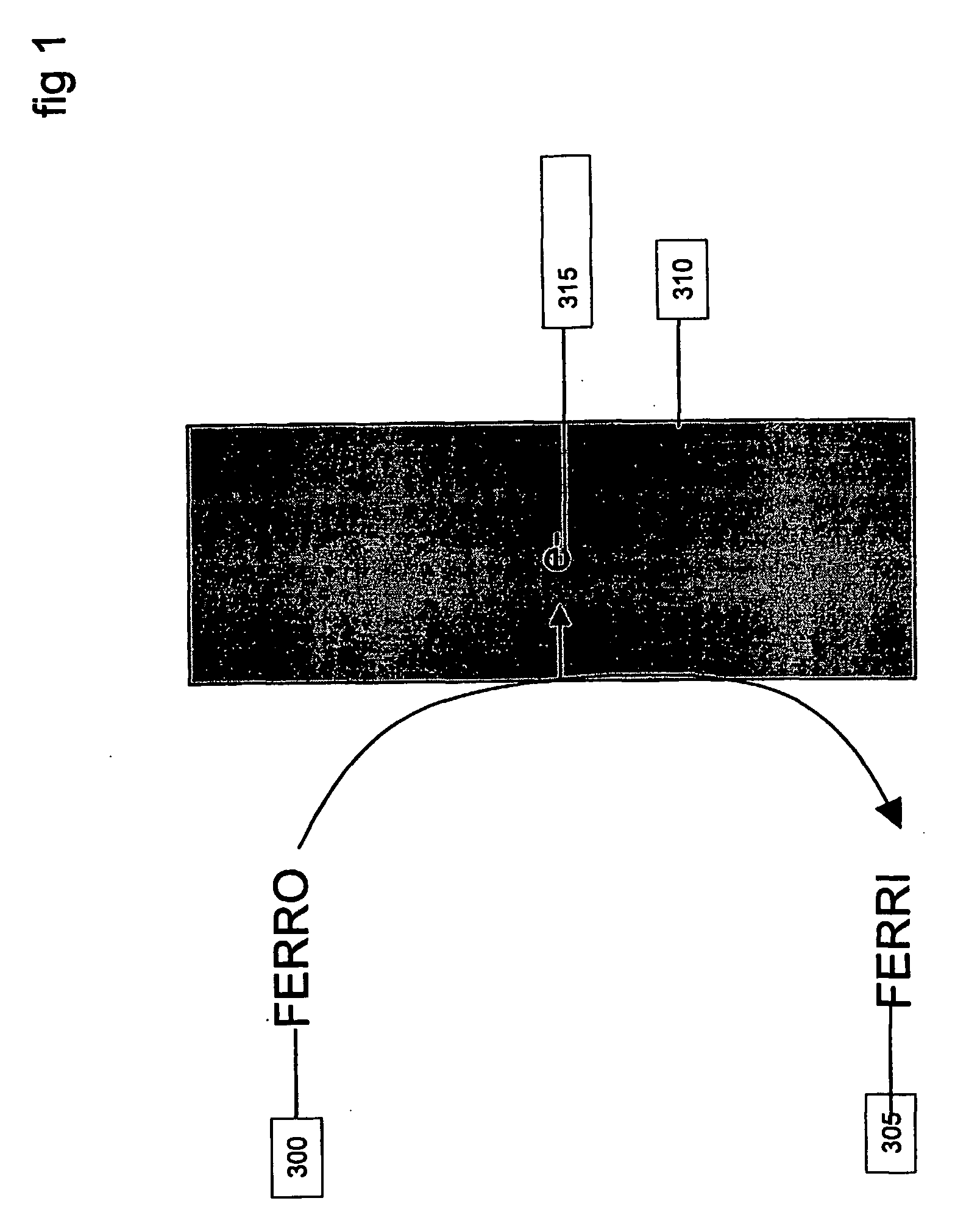
An example using the method of FIGS. 5 and 6 and system as carried out by, for example, a system of FIG. 7, is now described in terms of analyzing the concentration of a sample containing the analyte ferrocyanide and variable effective electrode area. The Faradaic reaction that is detected by a DC potential is given by:
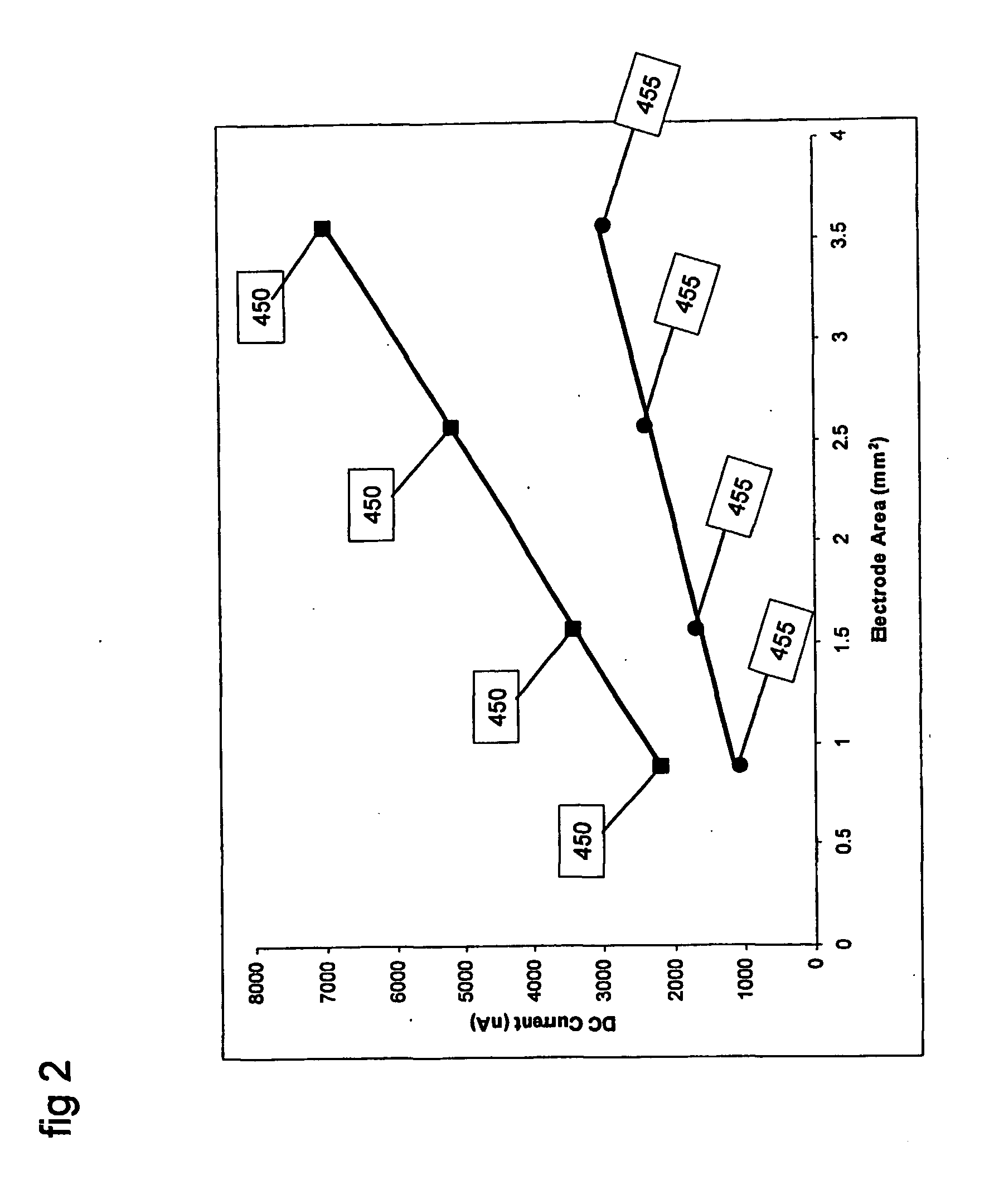
FERROCYANIDE→FERRICYANIDE+e− which is an oxidation reaction. The electrochemical cell may be a conventional 3-electrode set up with a palladium working electrode, platinum counter electrode, and a Ag / AgCl reference electrode. The working electrode may be held at a DC potential of −400 mV with respect to the reference electrode. FIG. 2 shows the DC current from two samples, one containing 10 mM FERRO and the other containing 20 mM FERRO, for measurements made with different effective electrode areas.
FIG. 2 shows the data points 450 that were measured by applying a DC potential of 400 mV to a sample containing 20 mM ferrocyanide. Measurements 450 were made with elect...
example 2
An example using the method of FIGS. 5 and 6 and system as carried out by, for example, a system of FIG. 7, is now described in terms of analyzing the concentration of a sample containing the analyte ferrocyanide and variable extent of electrode fouling. As in Example 1, the Faradaic reaction that is detected is the oxidation of ferrocyanide to ferricyanide, and an equivalent 3-electrode electrochemical system is used where the working electrode is a platinum electrode of 3.14 mm2. In this example, the effective electrode area may be kept constant and the extent of electrode fouling is varied to illustrate the effect of fouling on the measured signal and the estimated ferrocyanide concentration. A method is described to use capacitive signal information to correct for errors in ferrocyanide estimation that may arise due to electrode fouling.
The working electrode was fouled by coating the whole electrode area with a cellulose acetate (“CA”) membrane. The extent of electrode foulin...
example 3
Another example of a useful benefit of capacitance measurements is detecting when the sample changes. There may be situations in fuel tank storage where foreign material leaks into these tanks, as sown in FIG. 19. For example, it is not uncommon for water to seep into a fuel tank that contains petrol products. In some situations, the water and petrol are immiscible and each liquid separates into layers within the tank. This is shown in the figure by a layer of petrol 56 with a layer of water 58 on top. There may be a layer of air space 60 above that as well. If an array of electrodes 62, 64, 66, 68, 70, 72, 74 were lined along the side of the tank, then it may be possible to spatially resolve the distribution of the water layers within the petrol layers. One way in which this may be embodied is that by measuring the capacitance of each electrode system 62, 64, 66, 68, 70, 72, 74 by measuring the CDAS. In one example, this can be achieved by applying small amplitude high frequency s...
PUM
| Property | Measurement | Unit |
|---|---|---|
| total volume | aaaaa | aaaaa |
| frequency | aaaaa | aaaaa |
| admittance phase angle | aaaaa | aaaaa |
Abstract
Description
Claims
Application Information