
System and methods for inserting a vertebral spacer

a technology of vertebral spacer and system, which is applied in the field of vertebral spacer, can solve the problems of back pain, economic cost, alone exceeding $80 billion annually, etc., and achieve the effects of simple geometry, easy inserting into the intervertebral space, and simple geometry

Inactive Publication Date: 2005-03-31
ZYVOGEN LLC +1
View PDF51 Cites 46 Cited by
  • Summary
  • Abstract
  • Description
  • Claims
  • Application Information

AI Technical Summary

Benefits of technology

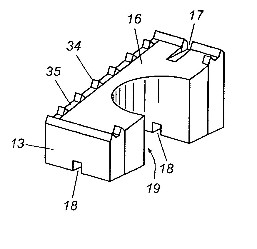
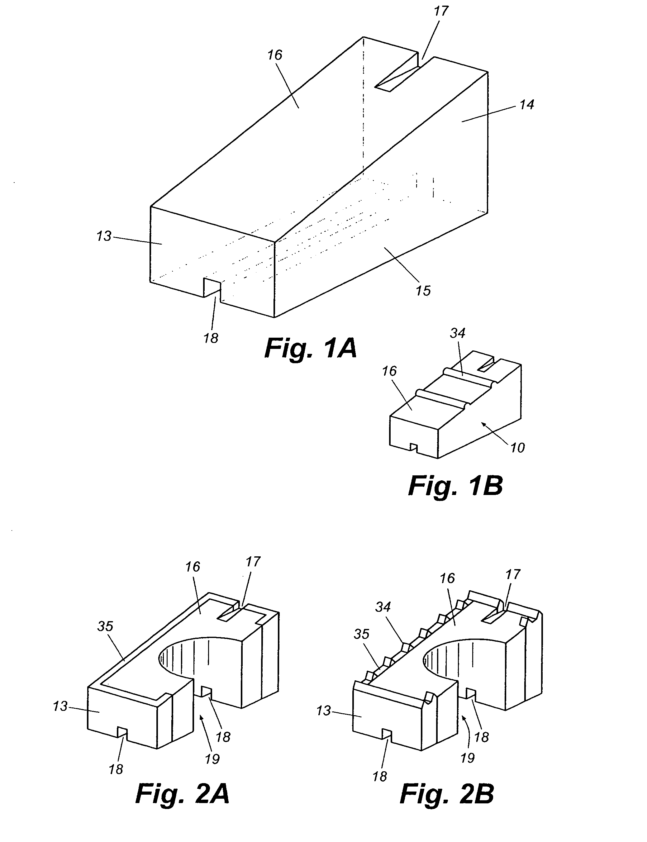
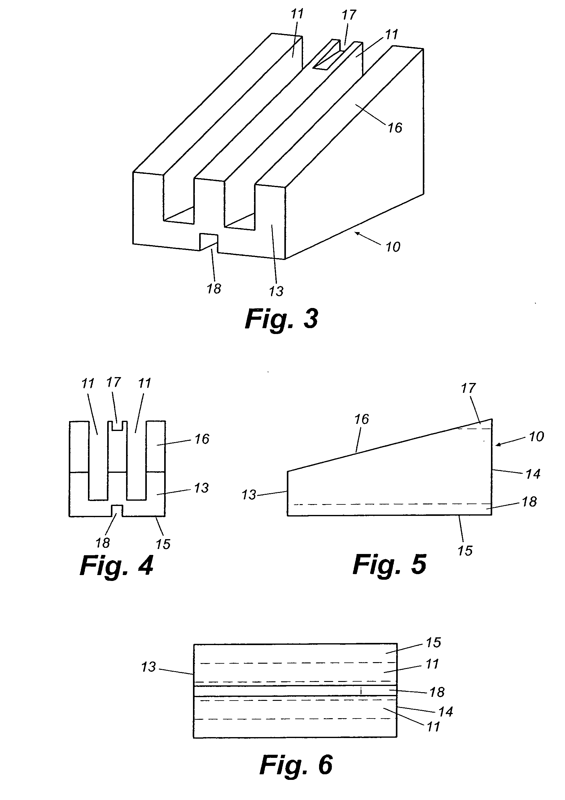
[0015] There is a need for a vertebral spacer having a simple geometry that is easily insertable into an intervertebral space while causing minimal trauma to the surface of the vertebrae as well as the bony processes thereof. The present invention provides a vertebral spacer having a simple geometry for supporting adjacent vertebrae after excision, at least partially or wholly, of an intervertebral disc. The spacer includes a body having a lower surface and an upper surface. The lower surface will be supported by a lower vertebra; the upper surface supports the adjacent upper vertebra. The body of the vertebral spacer of the present invention, therefore, provides support between the two adjacent vertebrae and to the spinal column.
[0024] The cutting tool is optionally slid along the channel of the insertion tool to engage a vertebra and generally is used to chisel at least one vertebral space receiving slot in the vertebrae. The cutting tool is removed from the patient by sliding the cutting tool back through the channel of the insertion tool. A vertebral spacer may then be slideably engaged with the insertion tool, with a space guide on the insertion tool engaging with a guiding groove of the vertebral spacer. The pusher may be engaged and advanced along the channel, thereby delivering the vertebral spacer into the vertebral spacer receiving slot (or receiving slots) in the adjacent vertebrae. It is also contemplated that a vertebral spacer receiving slot may not be cut in the adjacent vertebrae and that the inserted vertebral spacer optionally may contact only the uncut surface of the vertebrae.

Problems solved by technology

Back pain is one of the most significant problems facing the workforce in the United States today.
It is a leading cause of sickness-related absenteeism and is the main cause of disability for people aged between 19 and 45.
Published reports suggest that the economic cost is significant, treatment alone exceeding $80 billion annually.
The most common cause of disabling back pain, however, stems from trauma to a intervertebral disc, resulting from mechanical shock, stress, tumors or degenerative disease, which may impair functioning of the disc and limit spinal mobility.
In many cases, the disc is permanently damaged and the preferred treatment becomes partial or total excision.
Another cause of back injury is herniation of the intervertebral disc, wherein the gelatinous fluid of the nucleus pulposus enters the vertebral canal and pressures the spinal cord.
Traumatic injury to an intervertebral disc that is not removed will frequently promote scar tissue formation.
Scar tissue is weaker than original healthy tissue so that the disc will progressively degenerate, lose water content, stiffen and become less effective as a shock absorber.
Eventually, the disc may deform, herniate, or collapse, limiting flexibility of the spinal column at that position.
However, mechanical devices intended to replicate intervertebral disc function have had only limited success.
The disadvantage of such spacers is that stability is created at the expense of spinal flexibility.
Excessive removal of the bony process triggers further degradation and impediment of the normal movement of the spine.
The anterior approach to the spinal column is complicated by the internal organs that must be bypassed or circumvented to access the vertebrae.
Many intervertebral spacers require preparation of the surfaces of the adjacent vertebrae to accommodate the spacer, causing significant tissue and bone trauma.
They may also require screwing the spacer into the intervertebral space, making installation difficult and increasing trauma to the vertebral tissue.
Many spacers include complex geometries and are costly to manufacture.
Many of these complex spacers may require screwing the spacer into the intervertebral space, thereby making installation difficult and traumatic to the vertebral tissue.

Method used


Image

  • System and methods for inserting a vertebral spacer
  • System and methods for inserting a vertebral spacer
  • System and methods for inserting a vertebral spacer

Examples


Embodiment Construction

[0063] A full and enabling disclosure of the present invention, including the best mode known to the inventor of carrying out the invention, is set forth more particularly in the remainder of the specification, including reference to the accompanying drawings, wherein like reference numerals designate corresponding parts throughout several figures. This description is made for the purpose of illustrating the general principles of the invention and should not be taken in the limiting sense.

[0064] One aspect of the present invention is a vertebral spacer for insertion between two adjacent vertebrae 20, thereby maintaining the intervertebral space 23 and preventing compression of the spinal cord therein. Various embodiments of the vertebral spacer 10 in accordance with the present invention are shown in FIGS. 1A-22. The vertebral spacer 10 of the present invention is useful to replace an intervertebral disc 21 that has degenerated due to traumatic injury, vertebral displacement, or di...


PUM


Abstract

The present invention provides vertebral spacers having a lower surface and an upper surface, an anterior face and a posterior face extending from the lower surface, and at least one guiding groove for engaging an insertion tool. A system for delivering a vertebral spacer to the spinal column of a patient, includes an insertion tool, an optional guiding tool, a pusher, a vertebral spacer, and a cutting tool. The insertion tool accepts any of a pusher, a vertebral spacer, or a cutting tool and has at least one spacer guide for engaging with a guiding groove of a vertebral spacer. The vertebral spacer is inserted into a patient by inserting the insertion tool into an intervertebral space, engaging the guiding groove of a vertebral spacer with a space guide of the insertion tool, advancing a pusher into the insertion tool, thereby pushing the vertebral spacer into the intervertebral space and thereafter removing the pusher and the insertion tool. The cutting tool is optionally used to chisel at least one vertebral space receiving slot in the vertebrae. A hardening biocompatible composition also maybe delivered, to bond the vertebral spacer to an adjacent vertebra or be an osteogenic composition to promote bone growth.

Description

[0001] The present application claims the benefit of the provisional U.S. Application Ser. No. 60 / 231,142 filed Sep. 8, 2000, which is incorporated herein by reference in its entirety.FIELD OF INVENTION [0002] The present invention generally relates to a vertebral spacer to be inserted into an intervertebral space, thereby supporting the spinal column of a patient. The present invention further relates to a system and methods for implanting the vertebral spacer into the spinal column and securing the spacer therein. BACKGROUND OF THE INVENTION [0003] The spinal column, which is the central support to the vertebrate skeleton and a protective enclosure for the spinal cord, is a linear series of vertebral bones. Intervertebral discs separate and reduce friction between adjacent vertebrae and absorb compression forces applied to the spinal column. Spinal nerves that extend from each side of the spinal cord exit the column at intervertebral forama. [0004] A typical vertebra comprises an ...

Claims


Application Information

Patent Timeline
IPC IPC(8): A61F2/00A61F2/28A61F2/30A61F2/44A61F2/46
CPCA61F2/28A61F2310/00359A61F2/442A61F2/4611A61F2002/30131A61F2002/30153A61F2002/30158A61F2002/30266A61F2002/30448A61F2002/30492A61F2002/30507A61F2002/3051A61F2002/30785A61F2002/30828A61F2002/30841A61F2002/30879A61F2002/30919A61F2002/30971A61F2002/4627A61F2220/0025A61F2220/005A61F2230/0013A61F2230/0019A61F2230/0026A61F2230/0082A61F2310/00017A61F2310/00023A61F2310/00029A61F2310/00137A61F2310/00293A61F2310/00353A61F2/30965
Inventor MUHANNA, NABIL L.SCHALLIOL, DAVID L.
Owner ZYVOGEN LLC
Learn More