Micro-lens array and manufacturing method thereof

a micro-lens array and manufacturing method technology, applied in the field of micro-lens array manufacturing, can solve the problems of low productivity, difficult to manufacture a die for a lens having a high numerical aperture, low productivity, etc., and achieve the effect of high numerical aperture and simple process

Inactive Publication Date: 2005-04-07
SAMSUNG ELECTRONICS CO LTD
View PDF2 Cites 39 Cited by
  • Summary
  • Abstract
  • Description
  • Claims
  • Application Information

AI Technical Summary

Benefits of technology

[0014] The present invention provides a micro-lens array and a manufacturing method thereof, ...

Problems solved by technology

However, as the size of the lens is made smaller, it is difficult to manufacture a die for a lens having a high numerical aperture, that is, a die for an aspheric surface having a large radius of curvature.
Also, such a glass molding method has a disadvantage in that productivity is low because it takes a long time to uniformly heat a preform material through its interior.
However, the plastic material has a low refractive index of about 1.5, such that light refraction is insufficient.
Considerable time and effort are required to assemble and precisely adjust the position of the two lenses, thereby increasing manufacturing cost ...

Method used


Image

  • Micro-lens array and manufacturing method thereof
  • Micro-lens array and manufacturing method thereof
  • Micro-lens array and manufacturing method thereof

Examples


Embodiment Construction

[0042] The present invention will now be described more fully with reference to the accompanying drawings, in which exemplary embodiments of the invention are shown. The invention may, however, be embodied in many different forms and should not be construed as being limited to the embodiments set forth herein; rather, these embodiments are provided so that this disclosure will be thorough and complete, and will fully convey the concept of the invention to those skilled in the art. In the drawings, the thickness of layers and regions are exaggerated for clarity. Like reference numerals in the drawings denote like elements, and thus their description will be omitted.

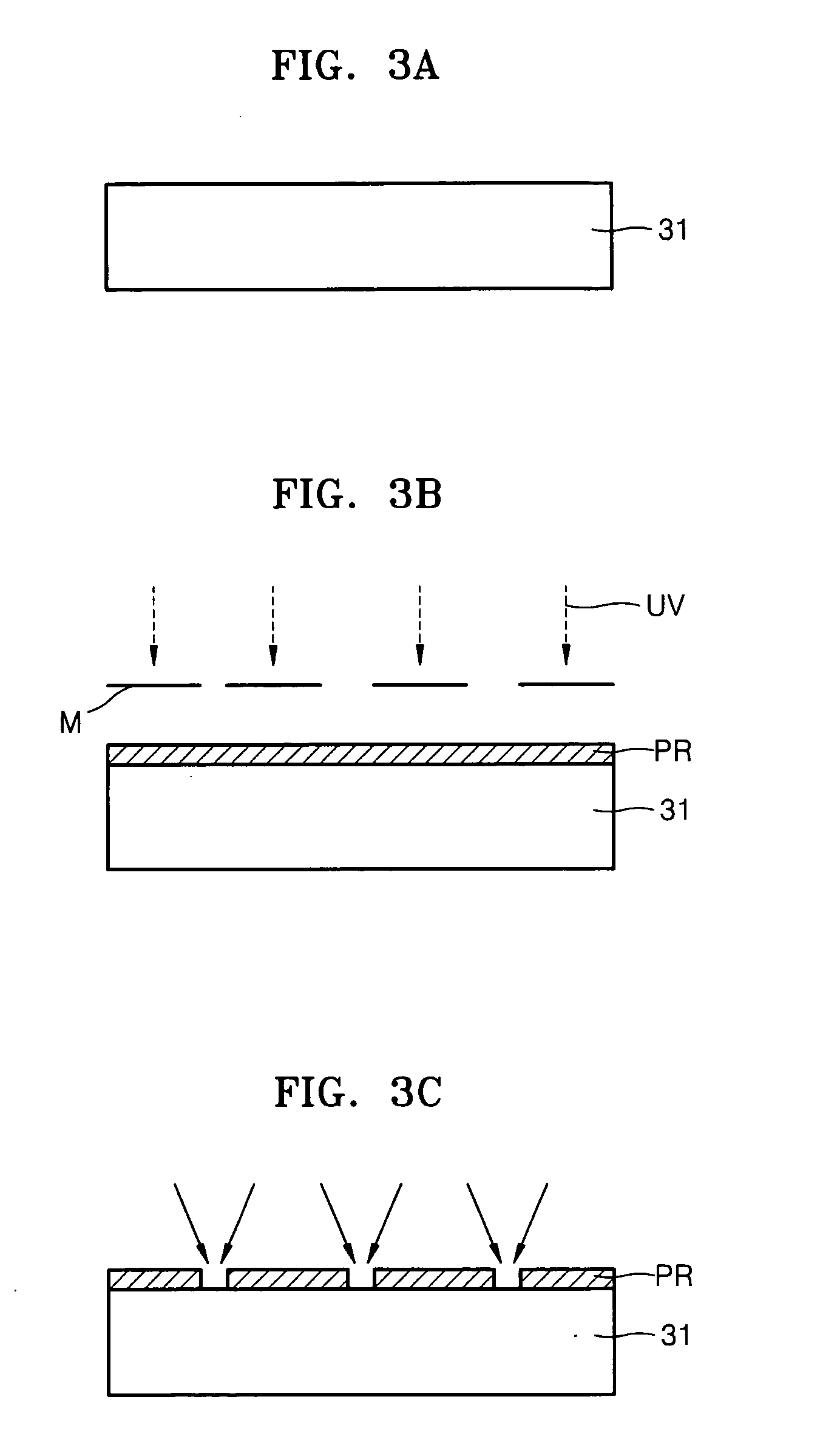
[0043]FIGS. 3A through 3F are sectional views illustrating sequential procedures of manufacturing a die for an aspheric lens array that is used in a micro-lens according to the present invention.

[0044] Referring to FIG. 3A, a substrate 31 is prepared. Preferably, the substrate 31 is formed of a glass-based material. Phot...


PUM

PropertyMeasurementUnit
Thicknessaaaaaaaaaa
Pressureaaaaaaaaaa
Transparencyaaaaaaaaaa

Abstract

A micro-lens array and manufacturing method. A hybrid micro-lens in which a refractive lens and a diffraction lens are formed includes: a refractive lens; a first ultraviolet hardening material which is bonded on a curved surface of the refractive lens to form an aspheric surface; a support substrate including a concave portion into which the refractive lens is inserted and supported; and a diffraction lens which is formed at a position corresponding to the refractive lens disposed on the support substrate.

Description

[0001] This application claims the priority of Korean Patent Application No. 2003-69729, filed on Oct. 7, 2003, in the Korean Intellectual Property Office, the disclosure of which is incorporated herein in its entirety by reference. BACKGROUND OF THE INVENTION [0002] 1. Field of the Invention [0003] The present invention relates to a method of manufacturing a micro-lens array, and more particularly, to a method of precisely manufacturing a micro-lens array including a micro-lens having a high numerical aperture. [0004] 2. Description of the Related Art [0005] A micro-lens may be manufactured by a method of forming a single micro-lens using a machining process, a method of forming a micro-lens array through a photolithography process using photoresist, etc. [0006] Among conventional methods of manufacturing a micro-lens, a machining process directly grinds or cuts glass or plastic material. Injection molding or press molding is used to mass-produce an object lens. The injection moldi...

Claims


Application Information

Patent Timeline
IPC IPC(8): B29C39/02B29D11/00B29L11/00G02B3/00G02B27/44
CPCB29D11/00278G02B3/0031G02B13/0085G02B5/1885G02B5/1852B29D11/00298G02B3/00
Inventor LEE, MYUNG-BOKSHON, JIN-SEUNGJUNG, MEE-SUKCHO, EUN-HYOUNGKIM, HAE-SUNG
Owner SAMSUNG ELECTRONICS CO LTD
Why Eureka
Try Eureka