
Treatment of liquid using porous polymer containment member

a porous polymer and containment member technology, applied in the field of treating liquid, can solve the problems of inability to make screens to contain small particles of media, and inability to manufacture membranes and filter paper robustness, so as to avoid the fabrication cost and/or limited strength of membranes, reduce the cost of manufacturing and operation, and reduce the effect of chemical species

Inactive Publication Date: 2005-04-14
MAGNESIUM ELEKTRON INC
View PDF72 Cites 18 Cited by
  • Summary
  • Abstract
  • Description
  • Claims
  • Application Information

AI Technical Summary

Benefits of technology

[0017] The following refers to specific features of the inventive media that apply to any aspect of the inventive article or method in this disclosure. The media may have an average particle size of not greater than about 50 microns and, in particular, an average particle size ranging from about 5-50 microns. The media comprises metal hydroxide or metal oxide. In particular, the media is based on zirconium, titanium or iron. More specifically, suitable media includes, but is not limited to, media selected from the group consisting zirconium dioxide, hydrous zirconium oxides, granular ferric hydroxide, hydrous ferric oxides, sulfur modified iron, hydrous titanium oxides, titanium dioxide, crystalline anatase, activated alumina and combinations thereof. The media is characterized by an ability to remove arsenic-containing chemical species from liquid to levels less than 2 parts per billion. The media can also include zirconium phosphates. Other suitable media is selected from the group consisting of: a) an amorphous zirconium phosphate of H-form that exhibits a peak at −13.7±0.5 ppm in the 31P NMR spectra; b) amorphous hydrous zirconium oxide having a pore size distribution ranging from 20 to 40 Å, a surface area of at least 150 m2 / g, an average particle size of at least 10 microns, and a stability against moisture loss characterized by a capacity and selectivity for chemical species that does not decrease more than 20% across a moisture content LOD ranging from 0<LOD<40%; c) zirconium phosphate of H form which is characterized by a 31P NMR spectra comprising peaks at −4.7 ppm and −17.0 ppm, each of the peaks being in a range of ±0.5 ppm, and combinations thereof.
[0029] The inventive system that includes the pH adjuster permits very high removal of chemical species over a long life of the device. The pH adjuster can operate as an acidifier or basifier and thus, may improve the performance of a variety of medias and enable efficient removal of a variety of chemical species in different liquids and applications.

Problems solved by technology

Screens cannot be made to contain small particles of media.
Membranes are expensive to fabricate and membranes and filter paper are not robust.
In applications such as drinking water treatment, failure of a membrane can result in breakthrough of the media bed and the hazard of drinking water containing toxins such as arsenic unknowingly entering the water supply.
If there is a thin section of the media bed such as might be caused by nonuniform charging of the media or irregularity in the porous containment material, a filtration device is self-correcting in that the thin section may become blocked and divert flow to other locations of the bed.
However, in the case of devices for treating water by adsorption or ion exchange, nonuniform beds of media are susceptible to breakthrough at regions of nonuniformity (e.g., thin sections), which leads to shortened life or hazardous operation of the device when used for removing toxic contaminants such as arsenic.

Method used


Image

  • Treatment of liquid using porous polymer containment member
  • Treatment of liquid using porous polymer containment member
  • Treatment of liquid using porous polymer containment member

Examples


Embodiment Construction

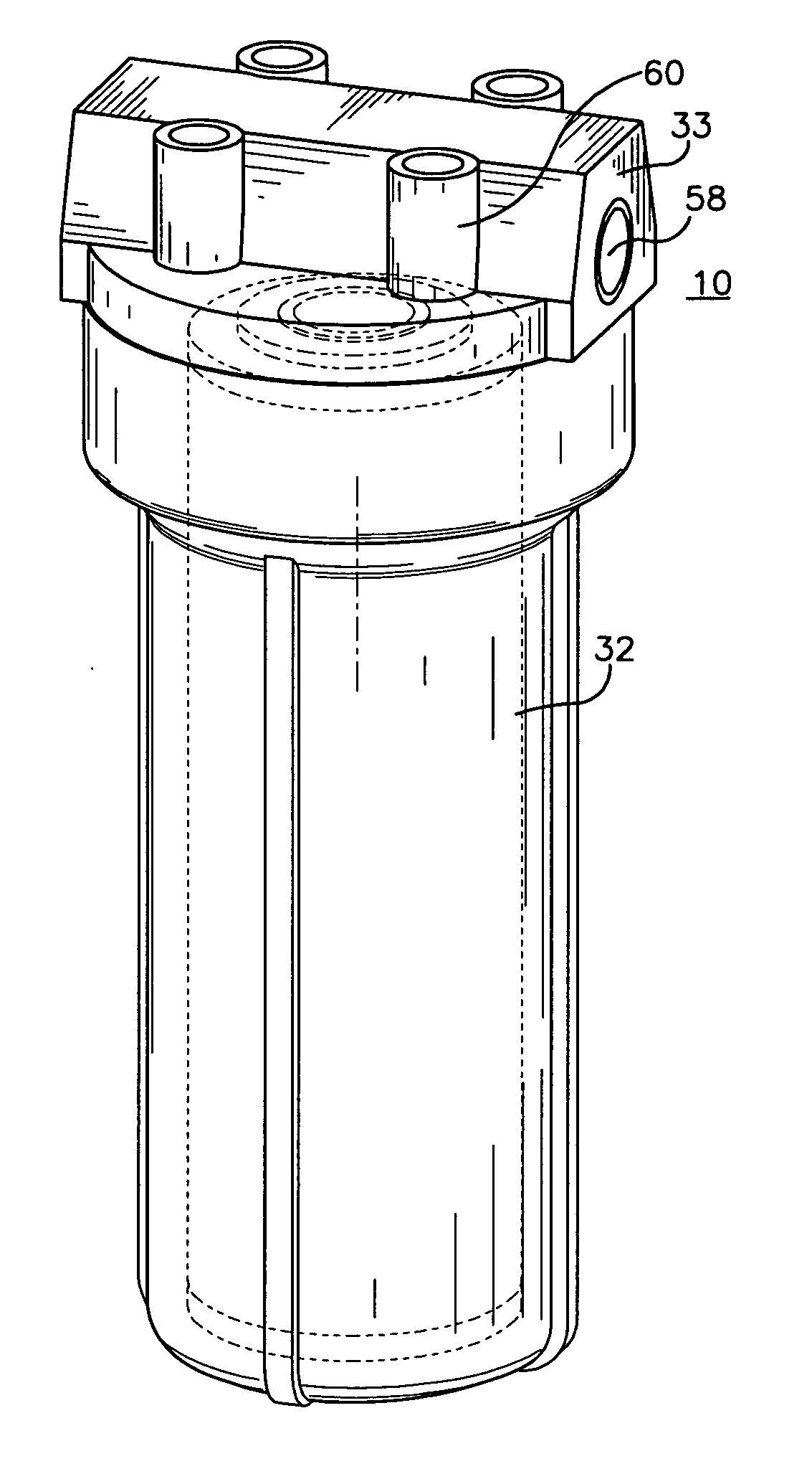
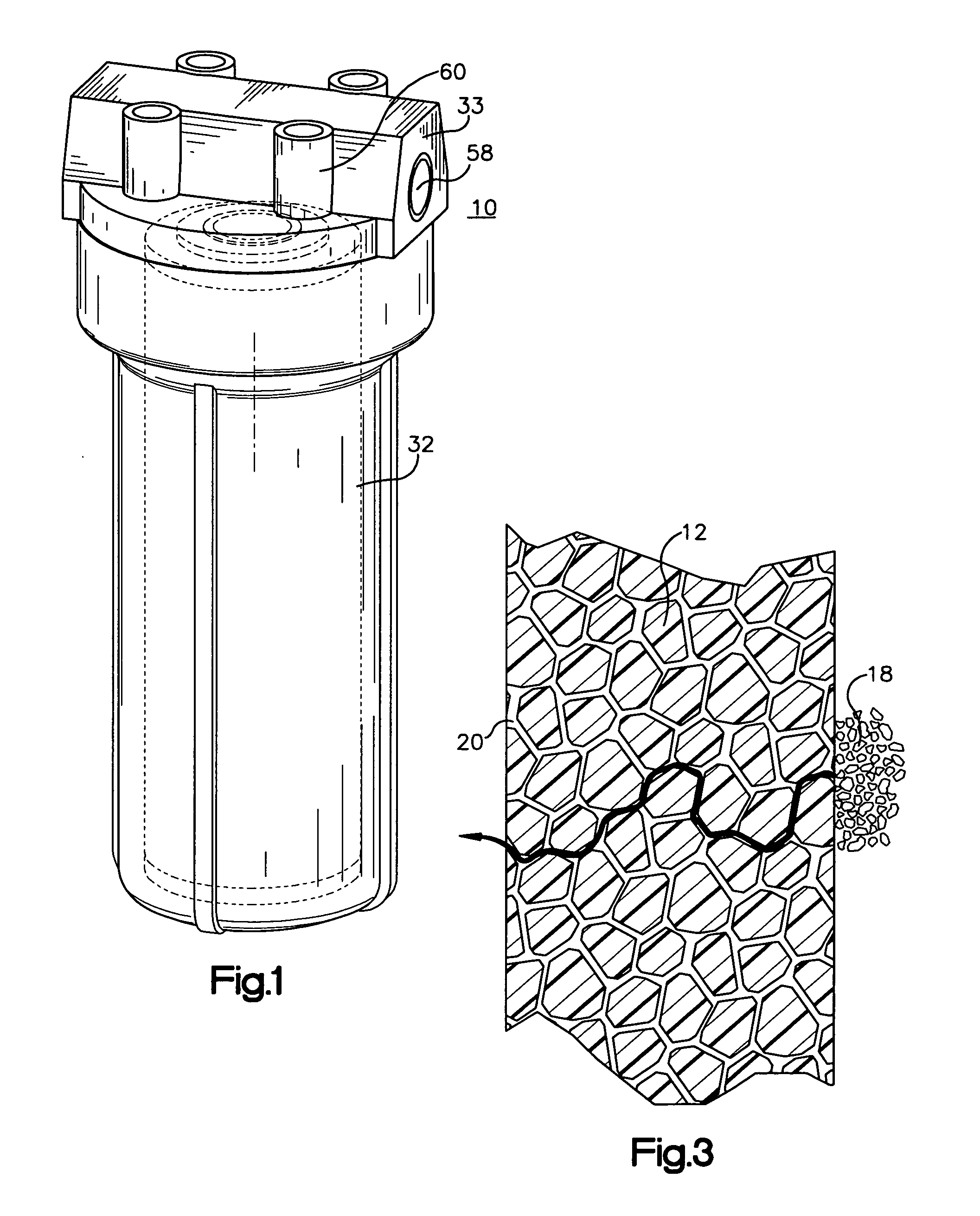
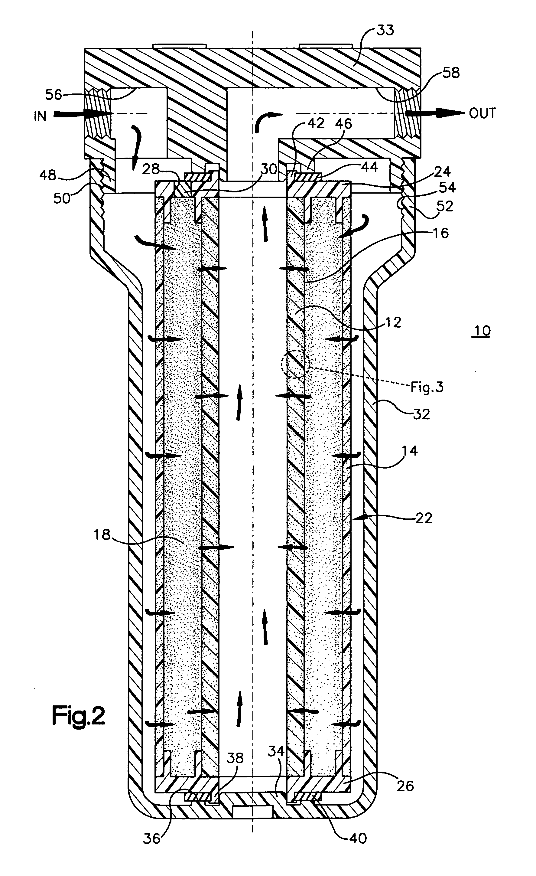
[0036] The present invention features a radial flow device 10 for treating liquids, comprising a containment member in the form of inner and outer porous polymer tubes 12, 14 (FIG. 2), which are constructed and arranged so as to form a generally annular space 16 between them. A generally annular bed of media 18 is contained in the space in contact with the first and second tubes. Pores in the porous polymer tubes are characterized by tortuous pore paths and pore sizes effective to permit flow of liquid through the pores while preventing media from traveling through the pores.

[0037] The inner tube 12 has a smaller diameter than the outer tube 14. The outer tube 14 is disposed around and concentric with the inner tube 12. Liquid travels generally radially through the porous polymer tubes and media as shown by the arrows in FIG. 2. In particular, influent or untreated liquid passes from outside the outer tube, generally radially through the outer tube, generally radially through the m...


PUM

PropertyMeasurementUnit
Fractionaaaaaaaaaa
Fractionaaaaaaaaaa
Fractionaaaaaaaaaa

Abstract

The present invention features a device for treating liquid including a containment member comprised of rigid porous polymer configured to form a containment space. Nonbonded particulate media is disposed in the space in contact with and contained by the containment member. Pores in the containment member are characterized by pore paths and pore sizes effective to permit flow of liquid through the pores while preventing the media from traveling through the pores. The containment member may be in various shapes and include different numbers of components. One variation of the containment member includes first and second containment layers comprised of the rigid porous polymer, which are configured and arranged so as to form a space therebetween in which the media is contained. Another variation of the containment member includes first and second porous polymer tubes forming a space in which the media is contained. Also featured is a method of using the device. Another aspect of the invention is a system that includes the device and a pH adjuster device that may function as an acidifier or basifier, which improves the performance of the liquid treatment device in removing substances from liquids by raising or lowering the pH of the influent traveling through the media of the liquid treatment device.

Description

RELATED INVENTIONS [0001] This is a continuation-in-part of co-pending U.S. patent application Ser. Nos. 10 / 195,630, filed Jul. 15, 2002; 10 / 195,875, filed Jul. 15, 2002 and 10 / 195,876, filed Jul. 15, 2002.FIELD OF THE INVENTION [0002] The present invention relates to treating liquid and, in particular, to removing substances from liquid, including dissolved substances. BACKGROUND OF THE INVENTION [0003] There are a myriad of filtration and water treatment devices that utilize a variety of containment materials and media. One device is disclosed in U.S. Pat. No. 4,104,170. This patent discloses particulate activated charcoal contained between inner and outer polypropylene paper in a tubular shape. The outer paper is in the form of pleats. The device requires a central core member in order to provide strength to the assembly. [0004] U.S. Pat. No. 5,082,568 discloses a water filter that includes a tubular block of bonded carbon. The outer surface of the block includes an inner wrap of...

Claims


Application Information

Patent Timeline
IPC IPC(8): B01J21/06B01J27/16B01J27/18B01J35/00B01J35/10B01J37/06B01J37/10B01J39/12B01J41/10C01B25/37C01G25/02C01G27/02C02F1/42
CPCB01D15/00B01J35/1061B01J20/08B01J21/063B01J21/066B01J27/16B01J27/18B01J35/002B01J35/0033B01J37/06B01J37/10B01J39/085B01J39/12B01J41/10B01J47/024B01J2220/62B01J2220/66C01B25/372C01G25/02C01G27/02C01P2002/02C01P2002/72C01P2004/61C01P2006/12C01P2006/16C01P2006/80C01P2006/82C02F1/281C02F1/42C02F1/66C02F2001/422C02F2101/20C02F2201/003B01J35/023B01J35/1014B01J20/06B01J39/09B01J35/30B01J35/33B01J35/40B01J35/613B01J35/647
Inventor PARDINI, JAMES J.FISCHER, FRANCIS J.
Owner MAGNESIUM ELEKTRON INC
Learn More