Surface discharge non-thermal plasma reactor and method

a plasma reactor and surface discharge technology, which is applied in the direction of arsenic compounds, silicon compounds, separation processes, etc., can solve the problems of unsatisfactory need for improving conversion efficiency, undesirable compounds in the exhaust stream of combustion processes, and in the exhaust stream of internal combustion engines

Inactive Publication Date: 2005-04-14
DELPHI TECH INC
View PDF7 Cites 20 Cited by
  • Summary
  • Abstract
  • Description
  • Claims
  • Application Information

AI Technical Summary

Benefits of technology

[0009] Surface discharge non-thermal plasma reactors employ one or more electrodes to produce surface plasma along the surfaces of the electrodes. In contrast to volume discharge non-thermal plasma devices, the surface discharge non-thermal plasma reactor can achieve an energy density of over 400 Townsend in the discharge region. The high field intensity achieved with the surface discharge reactor is sufficient to dissociate the nitrogen bond and lead to the production of nitric oxide. See, for example, Pietsch and Humpert, Discharge Mechanism and Ozone Generation by Surface Discharges Depending on Polarity, International Sympo

Problems solved by technology

Certain compounds in the exhaust stream of a combustion process, such as the exhaust stream from an internal combustion engine, are undesirable in that they must be controlled in order to meet government emissions regulations.
Under lean burn conditions, conventional catalytic devices are not very effective for treating the NOx in the resulting oxygen-rich exhaust stream.
In spite of efforts over the last decade to develop an effective catalyst for reducing NOx to nitrogen under oxidizing conditions in a spark ignition gasoline engine and in a diesel engine, the need for improved conversion effecti

Method used


Image

  • Surface discharge non-thermal plasma reactor and method
  • Surface discharge non-thermal plasma reactor and method
  • Surface discharge non-thermal plasma reactor and method

Examples


Embodiment Construction

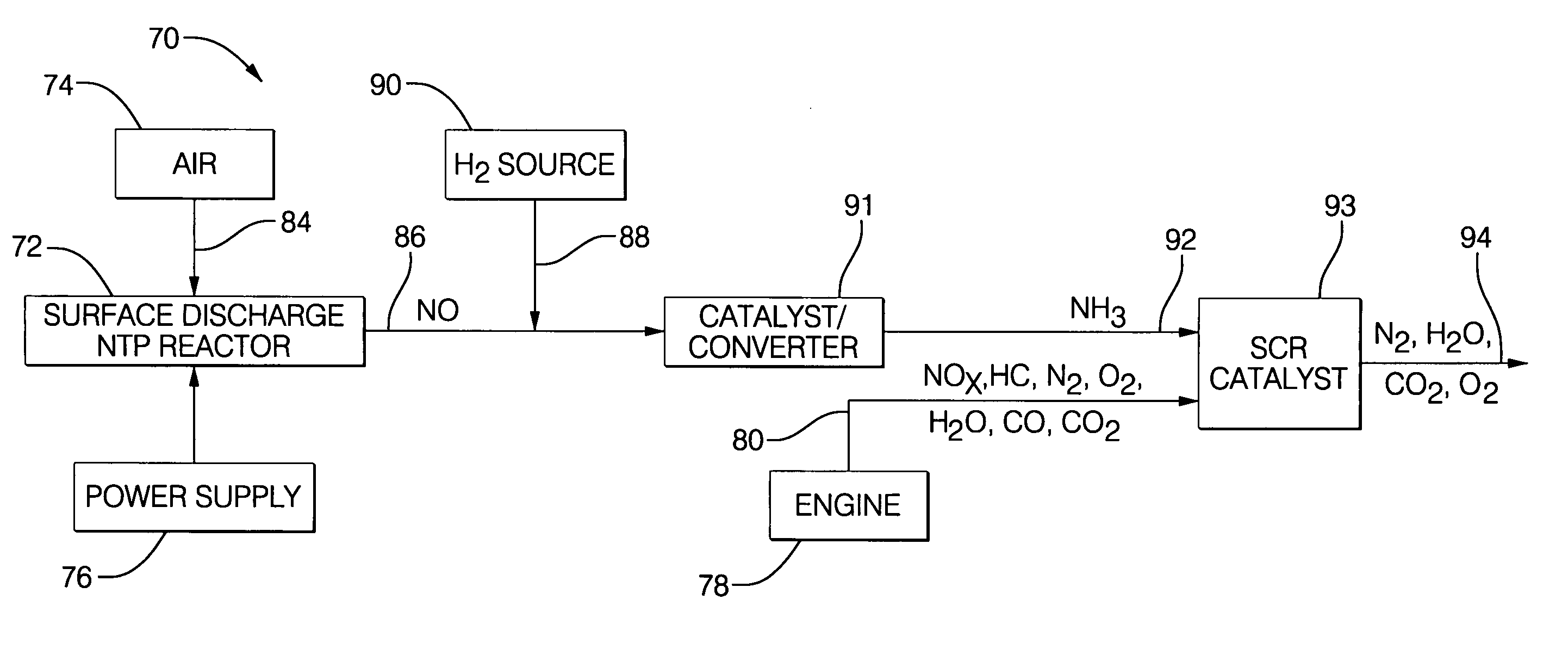
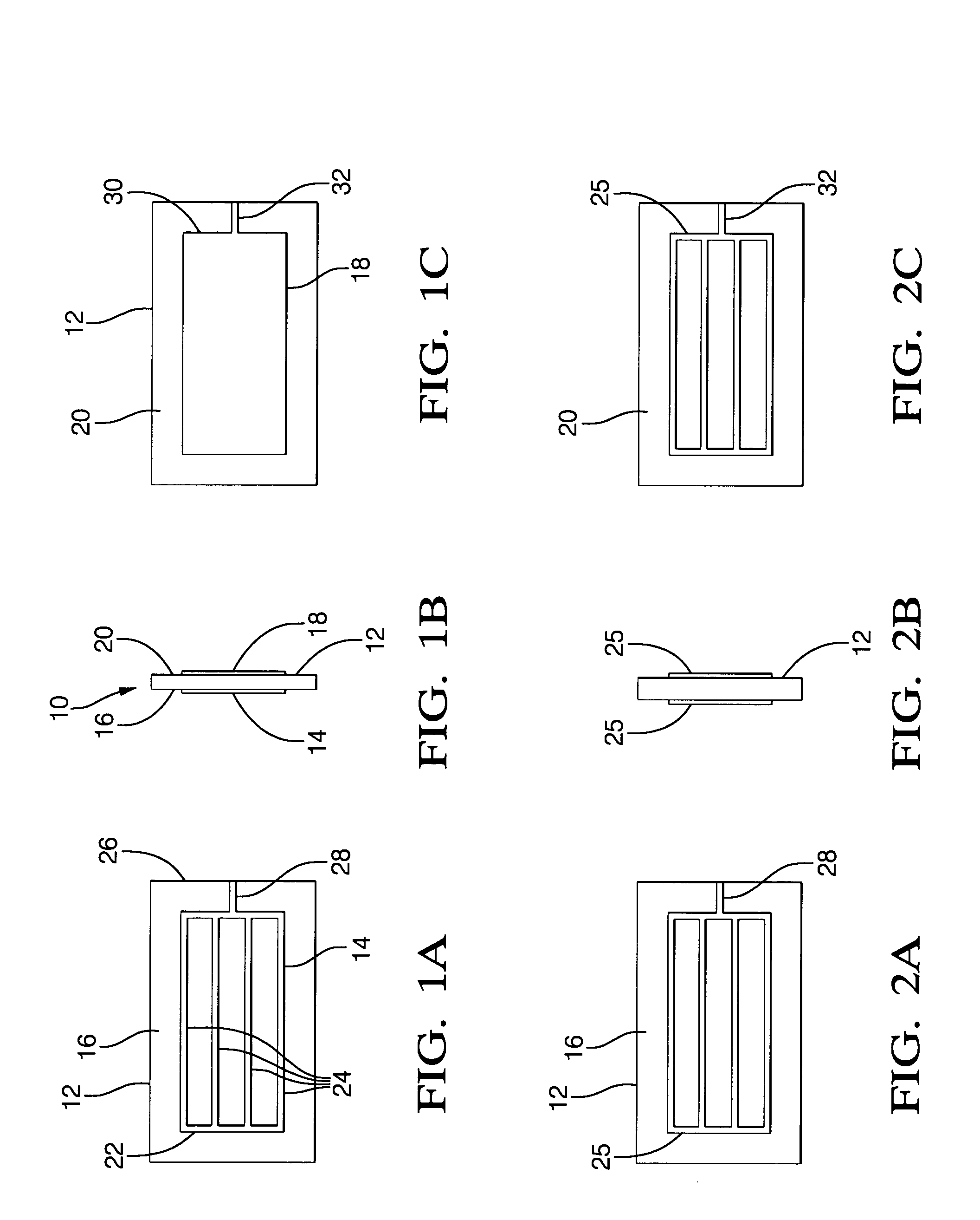
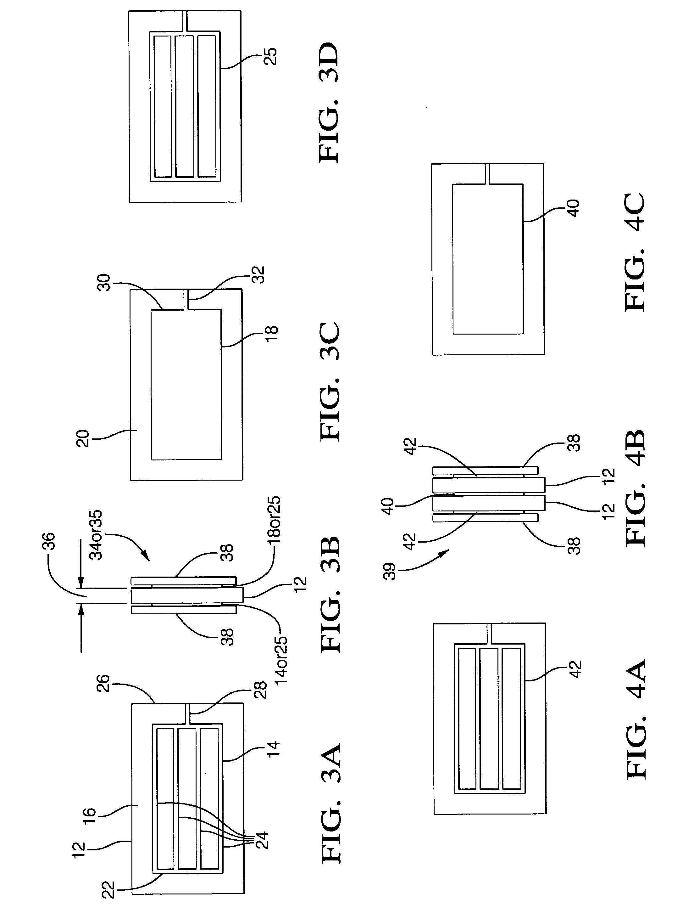
[0053] Surface discharge non-thermal plasma reactors in accordance with the present invention use surface discharge to generate a high intensity electric field for treating a nitrogen-containing gas stream (e.g., air). During treatment, the nitrogen bond is dislodged to form nitric oxide (NO) which can be used to produce ammonia for an SCR catalyst treatment device. Turning now to FIGS. 1A, 1B and 1C, a representation of a substrate and electrode pattern configuration 10 in accordance with one possible embodiment of the present invention includes a dielectric substrate 12 having a first electrode 14 printed on a first side 16 of the dielectric substrate 12 and a second electrode 18 printed on a second opposite side 20 of the dielectric substrate 12. The electrode 14 is disposed in a mesh pattern 22 comprising a plurality of parallel conductive strips 24 connected at one side 26 to a terminal lead 28 for connecting to a first polarity electrical busline (not shown). The electrode 18 ...


PUM

PropertyMeasurementUnit
Polarityaaaaaaaaaa
Volumeaaaaaaaaaa
Electrical conductoraaaaaaaaaa

Abstract

A surface discharge non-thermal plasma reactor includes a plurality of surface discharge reactor elements arranged in a stack and having a surface discharge gap formed between adjacent pairs of elements. Individual surface discharge elements include a dielectric substrate having disposed thereon first and second polarity surface discharge electrodes. Surface discharge electrode patterns and substrate configurations are provided to selectively control the volume of nitric oxide (NO) produced from a nitrogen-containing gas stream being treated in the reactor. In a preferred embodiment, surface discharge electrode and dielectric substrate configurations are arranged to maximize the production of NO. The surface discharge electrodes and substrates are combined and connected to a power supply to form various embodiments such as reactor stacks having a plurality of positive surface discharge gaps, reactor stacks having a plurality of negative surface discharge gaps, and reactor stacks having a plurality of alternating positive and negative surface discharge gaps.

Description

TECHNICAL FIELD [0001] The present invention relates generally to the treatment of nitrogen oxide (NOx) emissions from combustion exhaust gases, particularly combustion exhaust gases from diesel and other engines operating with lean air fuel mixtures that produce relatively high emission of NOx. More particularly, the invention relates to an on-board surface discharge non-thermal plasma reactor for generating NO to form ammonia which is used as a co-reductant in a selective catalytic reduction system and a method for fabricating the surface discharge non-thermal plasma reactor. BACKGROUND OF THE INVENTION [0002] Certain compounds in the exhaust stream of a combustion process, such as the exhaust stream from an internal combustion engine, are undesirable in that they must be controlled in order to meet government emissions regulations. Among the regulated compounds are hydrocarbons, soot particulates, and nitrogen oxide compounds (NOx). There are a wide variety of combustion processe...

Claims


Application Information

Patent Timeline
IPC IPC(8): B01D53/94B01J19/08C01B21/24
CPCB01D53/9431B01D2251/2062B01D2259/818B01J19/088B01J2219/0813B01J2219/0835Y10T29/49002B01J2219/0875B01J2219/0894B01J2219/0896C01B21/24H05H1/24B01J2219/0847H05H1/2437H05H1/2439
Inventor LI, BOB XIAOBINHEMINGWAY, MARK DAVID
Owner DELPHI TECH INC
Why Eureka
Try Eureka