
Radiation treatment using x-ray source

Active Publication Date: 2005-04-14
XOFT INC
View PDF15 Cites 66 Cited by
  • Summary
  • Abstract
  • Description
  • Claims
  • Application Information

AI Technical Summary

Benefits of technology

[0010] The use of a balloon catheter with contrast medium in or on the skin of the balloon, as opposed to being contained in a saline solution within the balloon, is a strong departure from the prior art. The advantage is that the physician will not over-dope the saline solution with contrast medium, thus maintaining the strength of the therapeutic radiation emitted from inside the balloon. The balloon wall has virtually no attenuating effect on the therapeutic radiation, when the radiation passes through the balloon in a normal or generally normal direction to the skin of the balloon. However, when the x-ray is taken from outside, the outline of the balloon will show up sharply because of the tangential direction of viewing that outline and the fact that the outline represents many times the wall thickness of the balloon, perhaps 20-40 times the density of contrast medium, thus contributing to the visible outline in the x-ray.

Problems solved by technology

With balloons limited to known geometries, there are limitations in the ability to treat a cavity margin thoroughly.
In some cases, the patient cannot take advantage of such a treatment protocol because the known-geometry balloon applicator simply cannot fill many surgical cavities that are irregular in shape.
Another limitation of known procedures using balloon catheters is in regard to locating the balloon correctly within a cavity of the patient, such as a resection cavity.
However, because the balloon shape is difficult to see in the x-ray, surgeons usually add the contrast material in a much higher concentration, not as contemplated by the dose plan, so as to better detect the balloon in the x-ray.

Method used


Image

  • Radiation treatment using x-ray source
  • Radiation treatment using x-ray source
  • Radiation treatment using x-ray source

Examples


Embodiment Construction

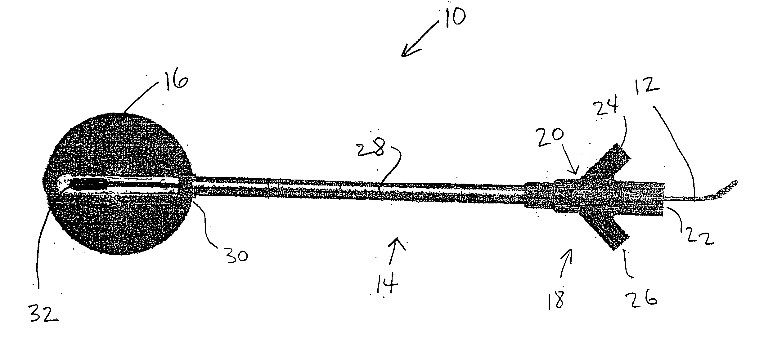
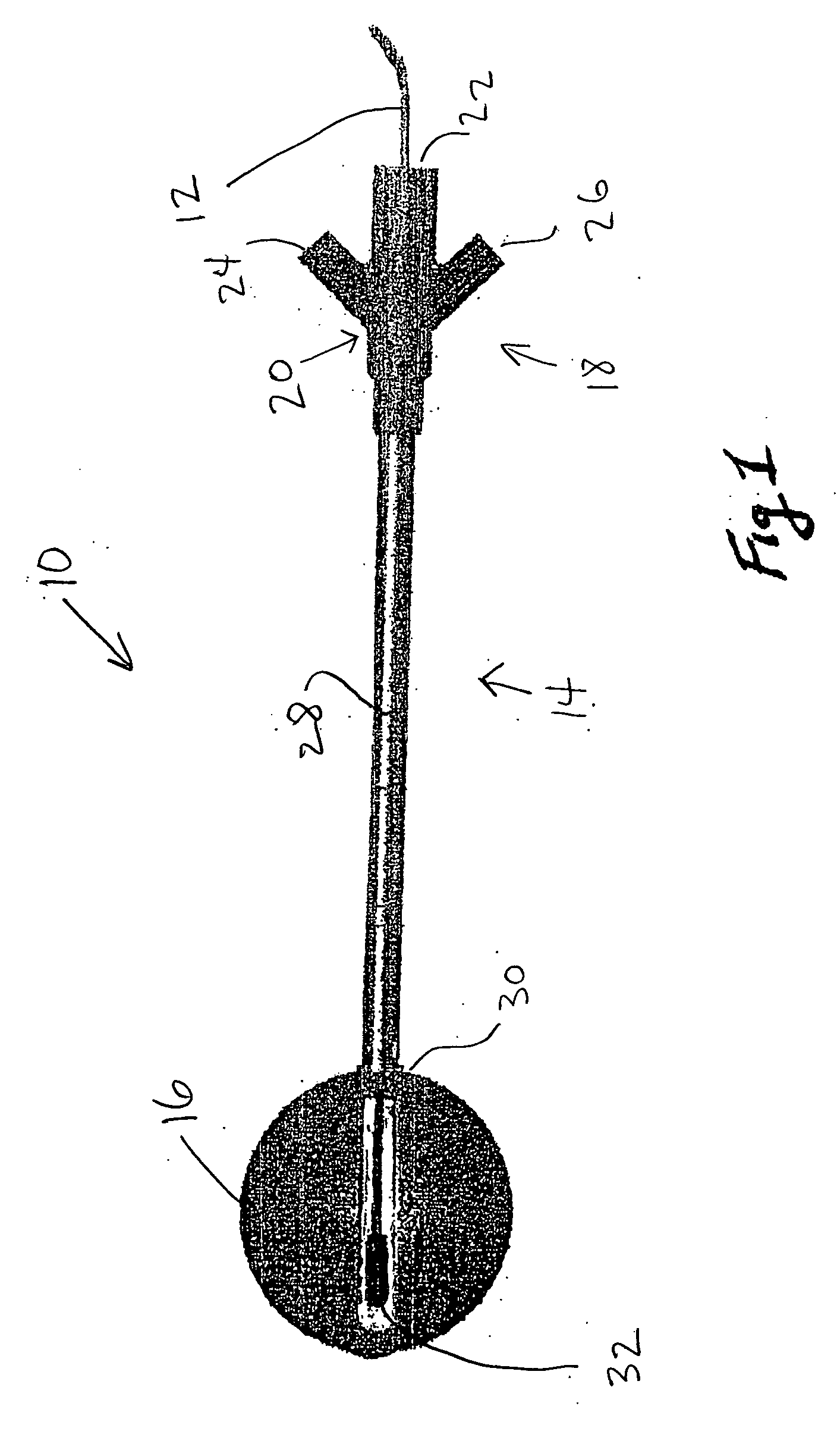
[0018] In the drawings, FIG. 1 shows somewhat schematically an applicator 10 according to one embodiment of the invention, the applicator including a flexible control line or cable 12 leading from a controller, not shown, and a catheter or applicator portion 14. A balloon 16 of the applicator and catheter is shown inflated in FIG. 1. The applicator device is generally as shown in co-pending application Ser. No. 10 / 683,885, filed Oct. 13, 2003.

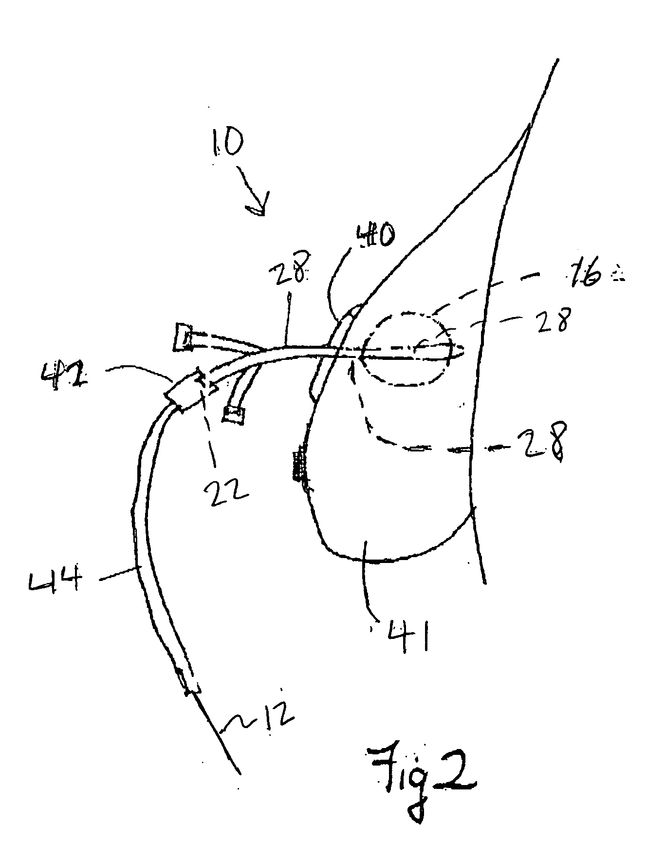
[0019] As shown, at the proximal end 18 of the applicator is a branch 20. The three ports 22, 24 and 26 of this branch device may comprise a service port, a drainage port and a balloon inflation port, respectively. The functions of these ports are explained further below with reference to other drawings.

[0020] A flexible main shaft 28 extends from the branch device 20 to the balloon 16, and is sealed to the balloon at 30. The balloon in FIG. 1 is shown partially cut away to reveal an electronic x-ray source 32 within the balloon, at the end o...


PUM


Abstract

Methods and apparatus are described for irradiating living tissue via a cavity or lumen, using an inflatable balloon applicator. In a preferred embodiment the applicator balloon has a balloon skin with x-ray contrast material in relatively low concentration, so that an outline of the balloon will appear sharply when imaged externally. In another preferred embodiment the balloon catheter has a drain for withdrawing liquids from the cavity, which may include channels or texture on the exterior of the balloon. Methods are described for using a switchable miniature x-ray tube, variable as to voltage and current, to achieve accuracy in an isodose profile.

Description

BACKGROUND OF THE INVENTION [0001] This application is a continuation in part of application Ser. No. 10,683,885, filed Oct. 13, 2003, now[0002] This invention concerns therapeutic radiation treatment of living tissue, usually but not necessarily within a body cavity, which may be a surgical cavity following a resection of a tumor. In one aspect the invention is concerned with use of a switchable, miniature electronic x-ray source, which may be controllable as to depth and intensity, for administering such therapeutic treatment. [0003] Treatment of surgical cavities, such as after malignant tumor excision, has been accomplished with applicators which are inserted usually into a newly formed opening through the skin, a conveniently located opening into the surgical resection cavity. Generally the location is different from the surgical closure itself. Applicators have been disclosed which essentially comprise a balloon of known and relatively rigid geometry, essentially spherical, ex...

Claims


Application Information

Patent Timeline
IPC IPC(8): A61B5/00A61B6/00A61B17/22A61B19/00A61M25/00A61M36/00A61NA61N5/10
CPCA61B19/54A61B2017/22051A61N2005/1061A61N5/1015A61N2005/1003A61B2019/5433A61B90/39A61B2090/3933
Inventor STEWART, DAREN L.LOVOI, PAUL A.RUSCH, THOMAS W.LIM, ALEXFRANCESCATTI, DARIUS
Owner XOFT INC
Learn More