Method and apparatus for determining access flow

a flow rate and access flow technology, applied in the direction of solvent extraction, other blood circulation devices, separation processes, etc., can solve the problems of poor flow rate, progressive reduction of treatment efficiency, poor flow of av fistulas, etc., and achieves less expensive, convenient operation, and easy implementation

Inactive Publication Date: 2005-04-21
GAMBRO LUNDIA AB
View PDF11 Cites 30 Cited by
  • Summary
  • Abstract
  • Description
  • Claims
  • Application Information

AI Technical Summary

Benefits of technology

[0016] On this background, it is the object of the present invention to provide a method of the kind referred to initially, which is less expensive, easier to implement and easier to operate. This object is achieved in accordance with claim 1 by creating a concentration difference between the blood and the dialysis liquid, and measuring the post dialyzer concentration or conductivity before and after a flow reversal. The creation of a difference in concentration for the purpose of measuring the fluid flow in the blood access allows for a significant increase in precision of the measurement.

Problems solved by technology

In the absence of a sufficient forward blood flow, the extracorporeal circuit blood pump will take up some of the already treated blood entering the fistula via the venous needle, so called access or fistula recirculation, leading to poor treatment results and progressive reduction of treatment efficiency.
A common cause of poor flow with AV fistulas is partial obstruction of the venous limb due to fibrosis secondary to multiple venipunctures.
It has been found that access flow rate often exhibit a long plateau time period with sufficient access flow, followed by a short period of a few weeks with markedly reduced access flow leading to recirculation and ultimately access failure.
However, these techniques require expensive equipment and are not easily used in the dialysis clinic environment.
Such methods have the disadvantage that they require the injection of the marker substance and external equipment for the measurements.
A disadvantage in these methods is the requirement for special equipment for measuring the urea concentration.
Urea sensors are as such available but they are not standard equipment for most of the dialysis monitors and they have also a considerable maintenance costs.

Method used


Image

  • Method and apparatus for determining access flow
  • Method and apparatus for determining access flow
  • Method and apparatus for determining access flow

Examples


Embodiment Construction

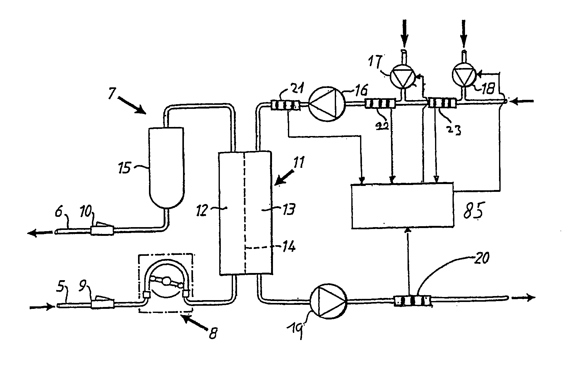
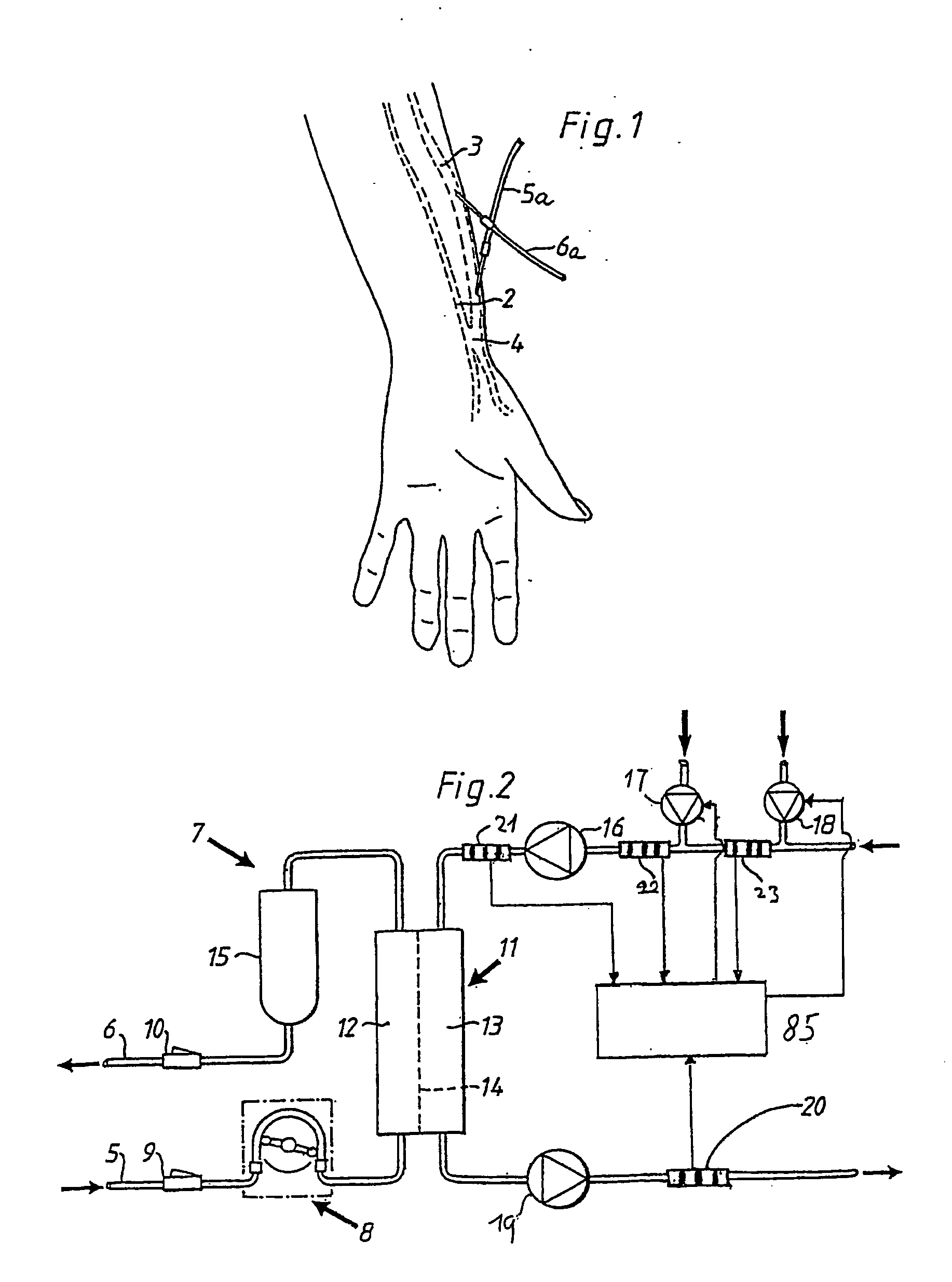
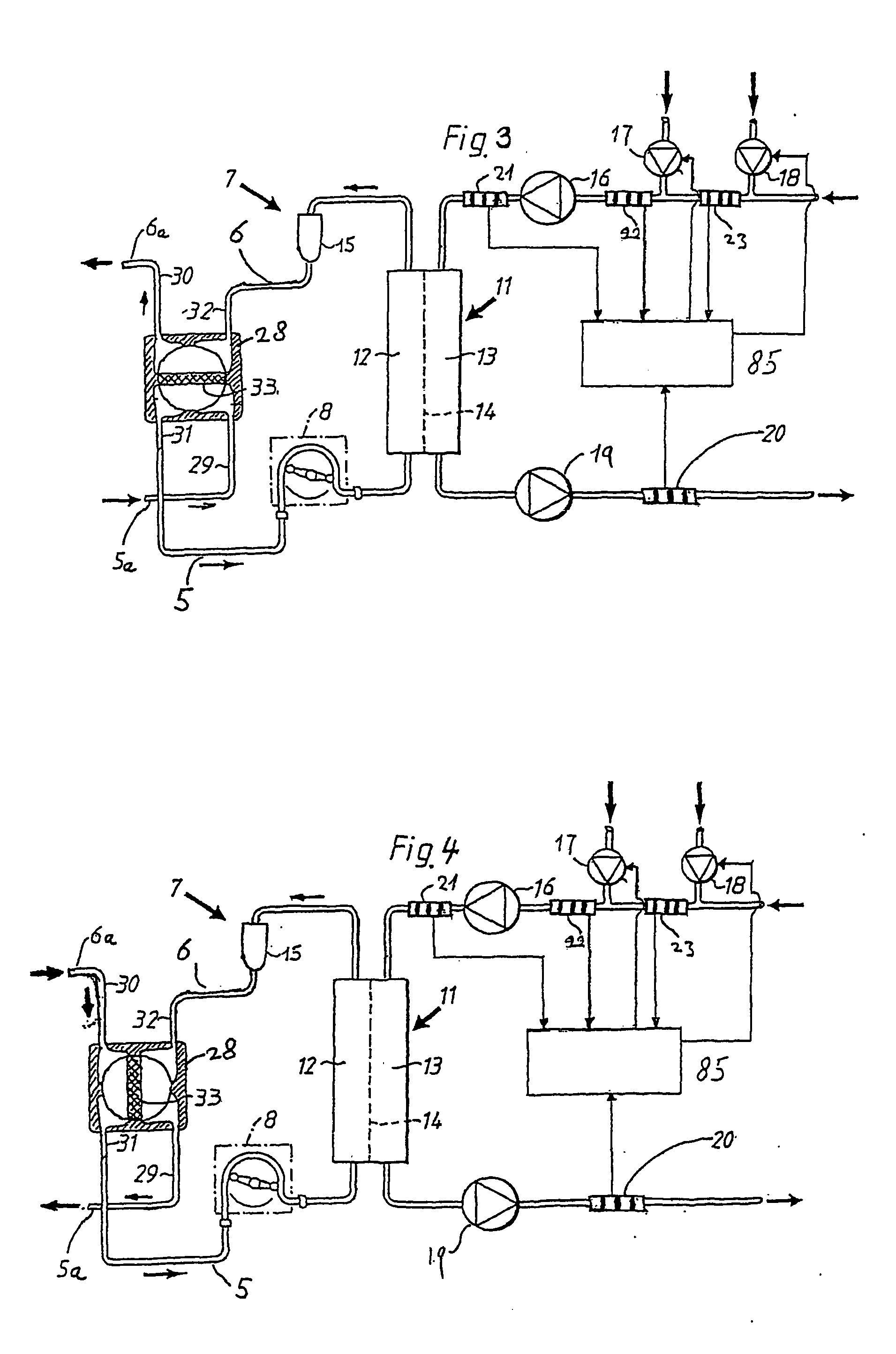
[0059] For the purpose of this description, a blood access is a site in which a fluid in a tube can be accessed and removed from and / or returned to the tube. The tube may be a blood vessel of a mammal, or any other tube in which a fluid is flowing. The general term blood access as used here includes arterio-venous fistulas, arterio-venous grafts, and dual-lumen catheters amongst other similar types of blood access that allow for an upstream access position and a downstream access position.

[0060] The general terms dialyzer or blood treatment unit as used here include filters for hemodialysis, hemofilters, hemodiafilters, plasmafilters and ultrafilters.

[0061] The fluid flow rate is the flow rate of the fluid in the tube or blood vessel immediately upstream of the blood access, denoted Qa.

[0062] The general term dialysis as used here includes hemodialysis, hemofiltration, hemodiafiltration and therapeutic plasma exchange (TPE), among other similar treatment procedures.

[0063] The ge...


PUM


Abstract

A method and apparatus for determining a fluid flow rate blood access having an upstream position and a downstream position using a dialysis system. The dialysis system includes a dialyzer having a semi permeable membrane delimiting a first chamber through which blood removed from said blood access passes, and a second chamber through which dialysis liquid passes. In addition, an arterial line and a venous line are connected to an inlet and an outlet of the first chamber, respectively.

Description

TECHNICAL FIELD [0001] The present invention relates to a method and apparatus for determining fluid flow rate in a patent's blood access. More particularly, the invention relates to the calculation of the fluid flow rate in the blood access based on conductivity measurements of the post dialyzer or other blood treatment unit effluent fluid. BACKGROUND ART [0002] There are several types of treatments in which blood is taken out in an extracorporeal blood circuit. Such treatments involve, for example, hemodialysis, hemofiltration, hemodiafiltration, plasmapheresis, blood component separation, blood oxygenation, etc. Normally, blood is removed from a blood vessel at a blood access and returned to the same blood vessel. [0003] In hemodialysis and similar treatments, a blood access commonly surgically created in the nature of a arterio-venous shunt, commonly referred to as a fistula. Blood needles are inserted in the fistula. Blood is taken out from the fistula via a needle at an upstre...

Claims


Application Information

Patent Timeline
Patent Type & Authority Applications(United States)
IPC IPC(8): A61M1/14A61M1/16A61M1/36
CPCA61M1/16A61M2205/13A61M1/3656A61M1/1605A61M1/1617A61M1/30A61M2202/0498A61M2205/15A61M2205/3317A61M2205/3324A61M2205/50A61M2230/65A61M1/34A61M5/168
Inventor BENE, BERNARDGOUX, NICOLASHERTZ, THOMASJANSSON, OLOFPERSSON, ROLANDSTERNBY, JANASBRINK, PERRY
Owner GAMBRO LUNDIA AB
Why Eureka
Try Eureka