Renesting interaction map into design for efficient long range calculations

Inactive Publication Date: 2005-04-28
GLOBALFOUNDRIES INC
View PDF20 Cites 29 Cited by
  • Summary
  • Abstract
  • Description
  • Claims
  • Application Information

AI Technical Summary

Benefits of technology

[0017] It is another object of the present invention to provide a model-based approach that efficiently, easily and cost effectively maintains a desired design data hierarchy regardless of ROI size.
[0018] Another object of the present invention is to provide a model-based approach that efficiently, easily and cost effectively rebuilds a design data hierarchy when a desired design data hierarch

Problems solved by technology

Since present lithography tools employ partially coherent illumination, such modeling is computationally intensive for all but elementary patterns.
However, optical proximity correction simulation kernels associated with lithographic processes for semiconductor chip manufacturing currently do not take into account the higher order aberrations, whose results may be realized in long-range effects, although not as prominent in the close-range of 1 to 2 micrometers.
Where flare effects are constant, a dose shift compensates for its effects completely; however, wherein it is not constant, any unacceptable variation in flare effects can diminish the circuit performance, and ultimately cause catastrophic failure.
However, representing each such shape separately poses a great challenge to the computer algorithms that are used on such mask shapes.
However, when the mask design needs to consider the very long range effect such as optical or chemical flare the interaction range becomes extremely large and consequently the neighborhoods of shapes that need to be regrouped becomes very large.
However, semiconductor wafer processes of

Method used


Image

  • Renesting interaction map into design for efficient long range calculations
  • Renesting interaction map into design for efficient long range calculations
  • Renesting interaction map into design for efficient long range calculations

Examples


Example

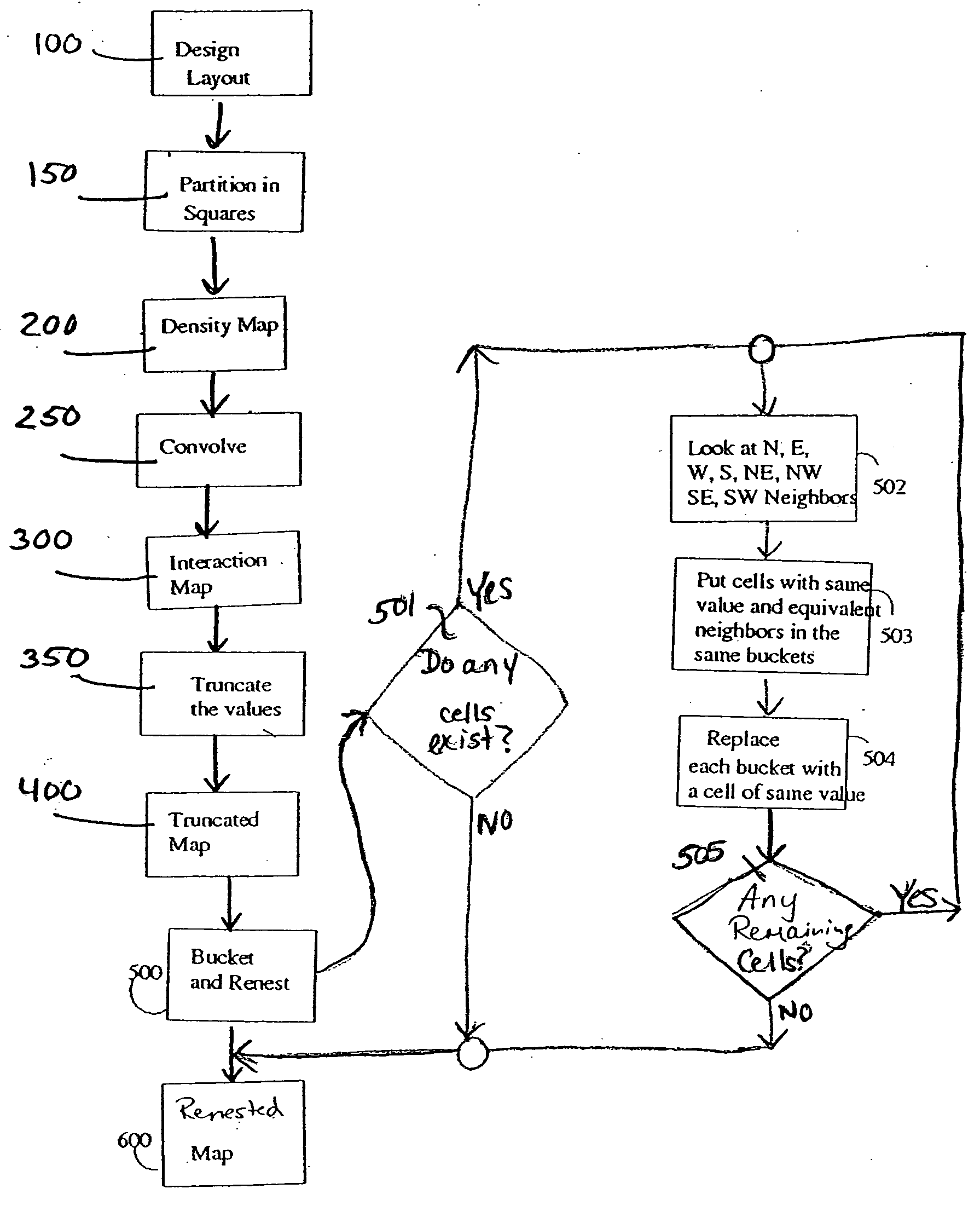
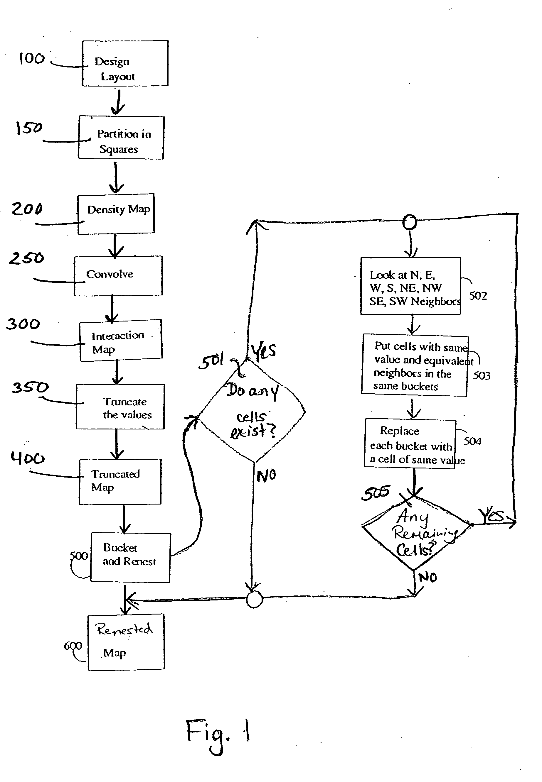
[0042] In describing the preferred embodiment of the present invention, reference will be made herein to FIGS. 1-4C of the drawings in which like numerals refer to like features of the invention.

[0043] The foregoing invention is ultimately for use in optical lithography to correct for any distortions on a photomask having desired circuit patterns, for the accurate projection thereof onto photoresist-coated wafers. In so doing, the invention provides model-based optical lithography simulations that enforce a desired design data hierarchy for long-range calculations, regardless of the size of the region of interest (ROI).

[0044] In accordance with the invention, the desired design data hierarchy is enforced by either maintaining an original, desired design data hierarchy or by rebuilding a design data hierarchy when the original, desired design data hierarchy has been either partially or completely destroyed, such as by processing conditions. However, the invention is particularly us...


PUM


Abstract

Methods, and program storage devices, for performing model-based optical lithography corrections by partitioning a cell array layout, having a plurality of polygons thereon, into a plurality of cells covering the layout. This layout is representative of a desired design data hierarchy. A density map is then generated corresponding to interactions between the polygons and plurality of cells, and then the densities within each cell are convolved. An interaction map is formed using the convolved densities, followed by truncating the interaction map to form a map of truncated cells. Substantially identical groupings of the truncated cells are then segregated respectively into differing ones of a plurality of buckets, whereby each of these buckets comprise a single set of identical groupings of truncated cells. A hierarchal arrangement is generated using these buckets, and the desired design data hierarchy enforced using the hierarchal arrangement to ultimately correct for optical lithography.

Description

CROSS-REFERENCE TO RELATED APPLICATIONS [0001] The present application is related to commonly assigned (Attorney Docket No. FIS920030107, titled “EXTENDING THE RANGE OF LITHOGRAPHIC SIMULATION INTEGRALS TO INCLUDE INTERMEDIATE DISTANCE SCALES”), U.S. patent application Ser. No. ______ (Attorney Docket No. FIS920030108, titled “INCORPORATION OF A PHASE MAP INTO FAST MODEL-BASED OPTICAL PROXIMITY CORRECTION SIMULATION KERNELS TO ACCOUNT FOR NEAR AND MID-RANGE FLARE”), U.S. patent application Ser. No. ______, (Attorney Docket No. FIS920030109, titled “IMPROVEMENT OF PERFORMANCE IN MODEL-BASED OPC ENGINE UTILIZING EFFICIENT POLYGON PINNING METHOD”, U.S. patent application Ser. No. ______, and U.S. patent application Ser. No. ______ (Attorney Docket No. FIS920030262, titled “SIMULTANEOUS COMPUTATION OF MULTIPLE POINTS ON ONE OR MULTIPLE CUT LINES”), filed on even date herewith, which are hereby incorporated by reference herein in their entirety.BACKGROUND OF THE INVENTION [0002] 1. Field...

Claims


Application Information

Patent Timeline
IPC IPC(8): G03F1/08G03F1/14G03F7/20G06F17/50H01L21/027H01L21/82
CPCG03F1/144G06F17/5068G03F1/36G03F1/68G06F30/39
Inventor GALLATIN, GREGG M.GOFMAN, EMANUELLAI, KAFAILAVIN, MARK A.MUKHERJEE, MAHARAJRAMM, DOVROSENBLUTH, ALAN E.SHLAFMAN, SHLOMO
Owner GLOBALFOUNDRIES INC
Why Eureka
Try Eureka