Compression ignition internal combustion engine

a technology of compression ignition and internal combustion engine, which is applied in the direction of machines/engines, electric control, mechanical equipment, etc., can solve the problems of noise reduction and decrease in combustion amount per unit time, and achieve the effects of reducing the passage sectional area of each injection hole, promoting atomization, and high fuel penetration for

Inactive Publication Date: 2005-05-05
DENSO CORP
View PDF3 Cites 24 Cited by
  • Summary
  • Abstract
  • Description
  • Claims
  • Application Information

AI Technical Summary

Benefits of technology

[0016] Since the number of the injection holes is increased, a passage sectional area of each injection hole is decreased and the atomization is promoted. In each injection hole group, the fuel is injected through adjacent injection holes in substantially the same direction. Therefore, the

Problems solved by technology

Meanwhile, a combustion amount per unit

Method used


Image

  • Compression ignition internal combustion engine
  • Compression ignition internal combustion engine
  • Compression ignition internal combustion engine

Examples


Embodiment Construction

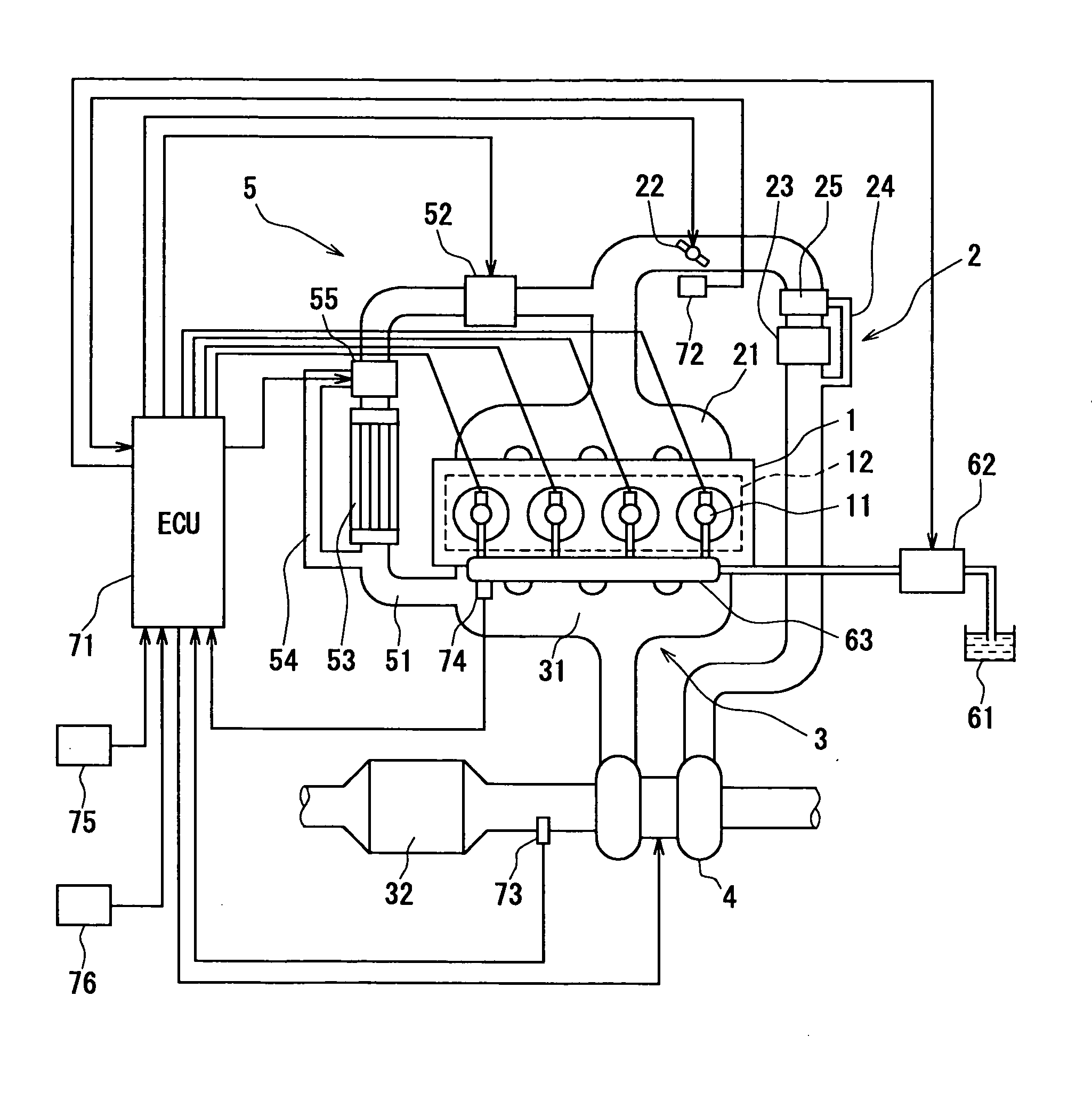
[0049] Referring to FIG. 1, a compression ignition engine having a fuel control system according to an embodiment of the present invention is illustrated. The present embodiment is applied to an automobile, for instance. The engine shown in FIG. 1 is a four-cylinder engine. Air is supplied into respective cylinders of an engine main body 1 from an intake system 2 and the air is consumed in combustion of the fuel. An intake manifold 21 communicating with the respective cylinders is disposed in a downstream end of the intake system 2. Intake quantity of the air is defined by an opening degree of a throttle valve 22. A variable valve mechanism 12 for regulating opening timing and closing timing of intake valves and exhaust valves is mounted to the engine main body 1.

[0050] Injectors 11 as supplying means are mounted to the respective cylinders on a one-on-one basis. The injector 11 injects the fuel when the injector 11 is open. The fuel is supplied from a common rail 63, which is comm...


PUM


Abstract

A compression ignition engine injects fuel through injection holes of an injector at a substantially constant injection rate to atomize the fuel so that the fuel can be easily vaporized and to make the fuel penetrate an atmosphere inside a cylinder. A spatial distribution of the injected fuel in which mixing of the fuel and air is promoted as the fuel recedes from the injection hole and the fuel reaches a premixing space where the fuel is premixed with the air is provided. The engine controls oxygen concentration inside the cylinder and an ignition delay so that a ratio of a quantity of the fuel injected before a start of ignition to a total fuel injection quantity falls within a range from 25% to 50% and so that the premixed gas formed in the premixing space is combusted serially.

Description

CROSS REFERENCE TO RELATED APPLICATION [0001] This application is based on and incorporates herein by reference Japanese Patent Applications No. 2003-373923 filed on Nov. 4, 2003 and No. 2004-247103 filed on Aug. 26, 2004. BACKGROUND OF THE INVENTION [0002] 1. Field of the Invention [0003] The present invention relates to a compression ignition internal combustion engine. [0004] 2. Description of Related Art [0005] In a compression ignition internal combustion engine, fuel injected from an injector in the form of liquid droplets is atomized and vaporized, and is mixed with air to form a combustible mixture gas. Then, the combustible mixture gas is ignited. Thus, the fuel is combusted in the compression ignition internal combustion engine. The injected fuel reaches a combustible state after the fuel is atomized and the combustible mixture gas is formed. Therefore, ignition timing lags behind fuel injection timing. More specifically, an ignition delay exists between the fuel injection...

Claims


Application Information

Patent Timeline
IPC IPC(8): F02D1/00F02D35/02F02B23/06F02D41/00F02D41/04F02D41/38F02D43/00F02M25/07F02M49/00F02M61/18
CPCF02B29/0418F02D35/02F02D41/005Y02T10/47F02M25/0728F02M61/182F02M25/0707F02M26/05F02M26/25Y02T10/40F02M49/00F02D1/00
Inventor SASAKI, SATORUKUBOSHIMA, TSUKASANAKAMURA, KANEHITOKINUGAWA, MASUMIKARIYA, YASUHIROKURONITA, TOKUJI
Owner DENSO CORP
Why Eureka
Try Eureka