Alignment stage apparatus

a technology of alignment stage and stage stopper, which is applied in the direction of motor/generator/converter stopper, dynamo-electric converter control, printer, etc., can solve the problems of reducing throughput, no battery mounted, disadvantageous in throughput, etc., and achieves high throughput, high throughput, and increased speed of movable stage

Inactive Publication Date: 2005-05-05
CANON KK
View PDF22 Cites 40 Cited by
  • Summary
  • Abstract
  • Description
  • Claims
  • Application Information

AI Technical Summary

Benefits of technology

[0024] According to the present invention, the plurality of power transmission coils to be electromagnetically coupled to the power reception coils attached to the movable stage are buried in the base structure. The power transmission coils are switched in accordance with the position of the movable stage. Therefore, power can be supplied from the base structure to the electric circuit on the movable stage at an arbitrary position or timing. When a battery is mounted on the movable stage main body, as the battery can be floating-charged, the stage need not be returned to a specific position for charging.

Problems solved by technology

Although a capacitor for keeping the voltage is mounted, since power consumption for electrostatic chucking is very small, no battery is mounted.
This prolongs the process interval of exposure or the like, or interrupts the process, to accordingly decrease the throughput.
This is disadvantageous in terms of throughput.
Also, in the conventional example described in Japanese Patent Laid-Open No. 8-51137, power can only be supplied at a specific position such as a stop position, and accordingly cannot be supplied at an arbitrary position or

Method used


Image

  • Alignment stage apparatus
  • Alignment stage apparatus
  • Alignment stage apparatus

Examples


first embodiment

[First Embodiment]

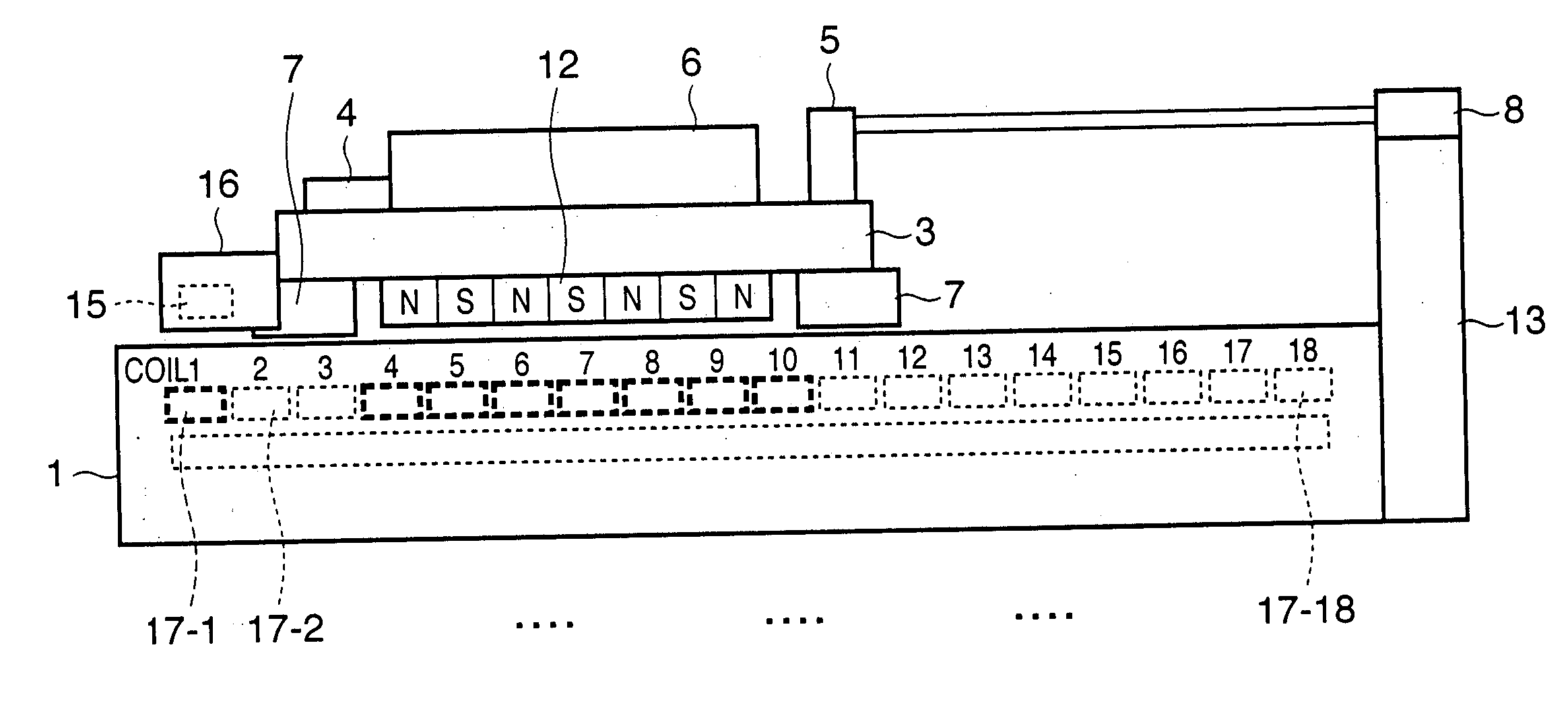
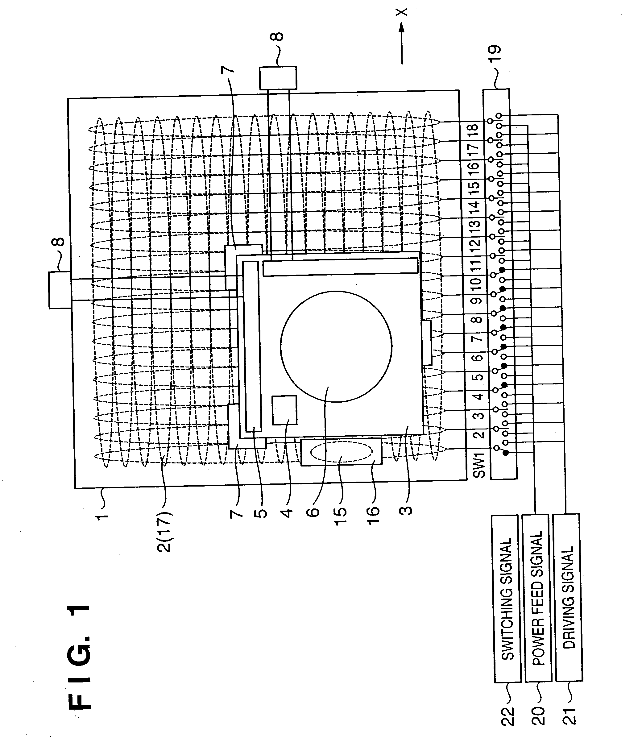
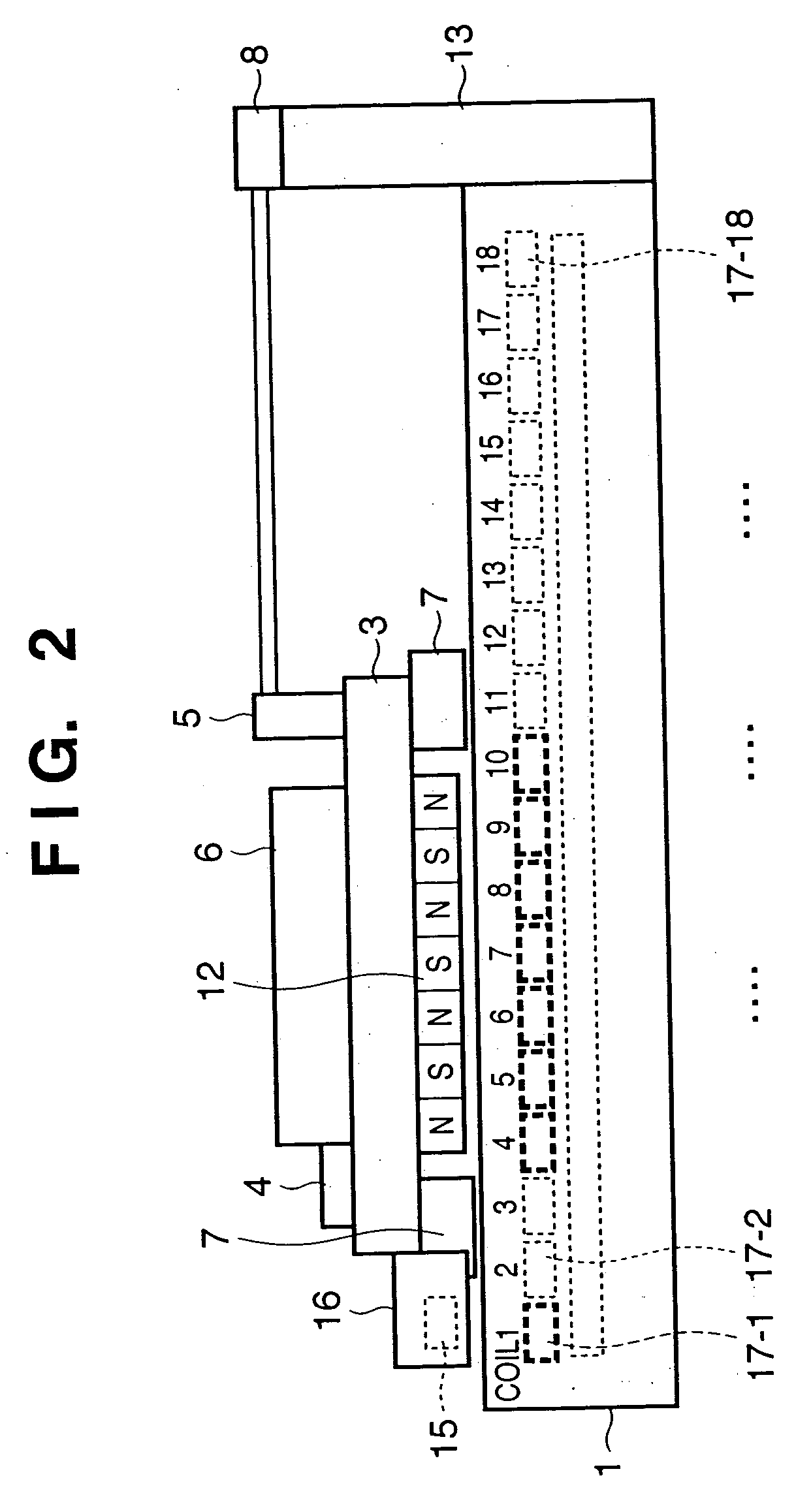
[0043]FIG. 1 is a plan view of an alignment stage apparatus according to an embodiment of the present invention, and FIG. 2 is a side view of the same. According to this alignment stage apparatus, a plurality of power transmission coils to supply power are buried in the base structure of an alignment stage having a power reception coil to which an AC magnetic field is to be applied to obtain power in a non-contact manner. The alignment stage apparatus is provided with a means for sequentially switching the power transmission coils in accordance with the position of the stage.

[0044] More specifically, in the alignment stage apparatus of FIG. 1, coils 2 are arranged like a matrix in a base structure 1. Permanent magnets 12 are similarly arranged like a matrix under a movable stage main body 3. When a current is supplied to the driving coils 2, the movable stage main body 3 obtains a thrust by the Lorentz force and is driven.

[0045] An electrostatic chuck 6 which hol...

second embodiment

[Second Embodiment]

[0053]FIG. 4 shows transmission and reception of a control signal using electromagnetic induction. The electrostatic chuck 6 and sensors 4 are mounted on the movable stage main body 3 of FIGS. 1 and 2. The control device (not shown) provided to the stationary side (base structure side) must also transmit and receive a signal to and from the electrostatic chuck 6 and sensors 4. When exchanging the wafer, voltage application to the electrostatic chuck 6 is disconnected to release a chucked wafer. A chuck on / off circuit 25 is provided for this purpose. An analog signal loaded from the sensors 4 is converted into a digital signal by an A / D (analog-to-digital) converter 24.

[0054] If transmission / reception circuits 26 are respectively provided to power transmission coils 17 and a power reception coil 15 and communicate with each other by superposing signals on the coils 17 and 15 to which power is supplied, the control signal can be exchanged by electromagnetic inducti...

third embodiment

[Third Embodiment]

[0055]FIG. 5 shows the third embodiment of the present invention. In the first embodiment, only one power reception coil 15 is provided. When the movable stage main body 3 moves, the power reception coil 15 gradually shifts from the position where it opposes the coil 17-1. Accordingly, power transmission efficiency by means of electromagnetic induction decreases.

[0056] In order to compensate for this, a power reception coil 15a is added in the second embodiment. The power reception coil 15a is arranged to be phase-shifted from power transmission coils 17. When the two power reception coils, i.e., a power reception coil 15 and the power reception coil 15a, are arranged in the traveling direction of the stage, if the power reception coil 15a is phase-shifted from the power transmission coils 17 by 90°, the fluctuations. (ripple) of the total power of the two different-phase coils can be decreased. Similarly, when three power reception coils can be arranged in the tr...


PUM


Abstract

Power is supplied at an arbitrary position of a movable stage main body or arbitrary timing by downsizing or removing a battery mounted on a movable stage main body, in a non-contact manner without using any electrical cable. In an alignment stage having a power reception coil to which an AC magnetic field is supplied to obtain power in a non-contact manner, a plurality of power transmission coils which supply power are buried in a base structure. An unit for sequentially switching the power transmission coils in accordance with a position of the stage is provided. The power reception coils on the stage include a plurality of power transmission coils arranged to be phase-shifted from the power transmission coils. The frequency of the AC magnetic field is set at a resonance frequency determined by a load and the mutual inductance of the power transmission coils and power reception coils.

Description

CLAIMS OF PRIORITY [0001] This application claims priority from Japanese Patent Application No. 2004-016857 filed Jan. 26, 2004, the entire contents of which are hereby incorporated by reference herein. FIELD OF THE INVENTION [0002] The present invention relates to an alignment stage apparatus used in a device manufacturing apparatus or the like which manufactures a device having a fine pattern, e.g., a semiconductor device. BACKGROUND OF THE INVENTION [0003] Japanese Patent Laid-Open No. 10-270535 shows the structure of an alignment stage apparatus in a semiconductor exposure apparatus. FIG. 7 is a plan view of the alignment stage apparatus described in Japanese Patent Laid-Open No. 10-270535, and FIG. 8 is a side view of the same. [0004] In the conventional alignment stage apparatus as shown in FIG. 7, coils 102 are arranged like a matrix in a base structure 101, and permanent magnets 112 are similarly arranged like a matrix under a movable stage main body 103. When a current is s...

Claims


Application Information

Patent Timeline
IPC IPC(8): H01L21/027G03F7/20G03F9/00H01L21/68
CPCG03F7/70716G03F7/70725H01L21/682G03F7/70991G03F9/7096G03F7/70758D05B35/06D05C7/08
Inventor OHISHI, SHINJI
Owner CANON KK
Why Eureka
Try Eureka