Thermal management apparatus and uses thereof

a technology of thermal management and equipment, applied in the field of thermal management equipment, can solve the problems of temperature gradient, axial cooling system, and general limitation to only covering 15% to 25% of the volum

Active Publication Date: 2005-05-05
GE MEDICAL SYST GLOBAL TECH CO LLC
View PDF27 Cites 22 Cited by
  • Summary
  • Abstract
  • Description
  • Claims
  • Application Information

AI Technical Summary

Benefits of technology

[0006] The present invention therefore provides, in some configurations, a cooling assembly for an electrical component. The assembly includes a non-magnetic, thermally conducting spreader substrate, and at...

Problems solved by technology

However, axial cooling systems (i.e., cooling tubes placed along a z-axis, nominally parallel to a head-to-toe patient axis), for example, are generally limited to covering only 15% to 25% of the volume of the MRI system due to bending limitations of the cooling tubes.
The limited volume...

Method used


Image

  • Thermal management apparatus and uses thereof
  • Thermal management apparatus and uses thereof
  • Thermal management apparatus and uses thereof

Examples


Embodiment Construction

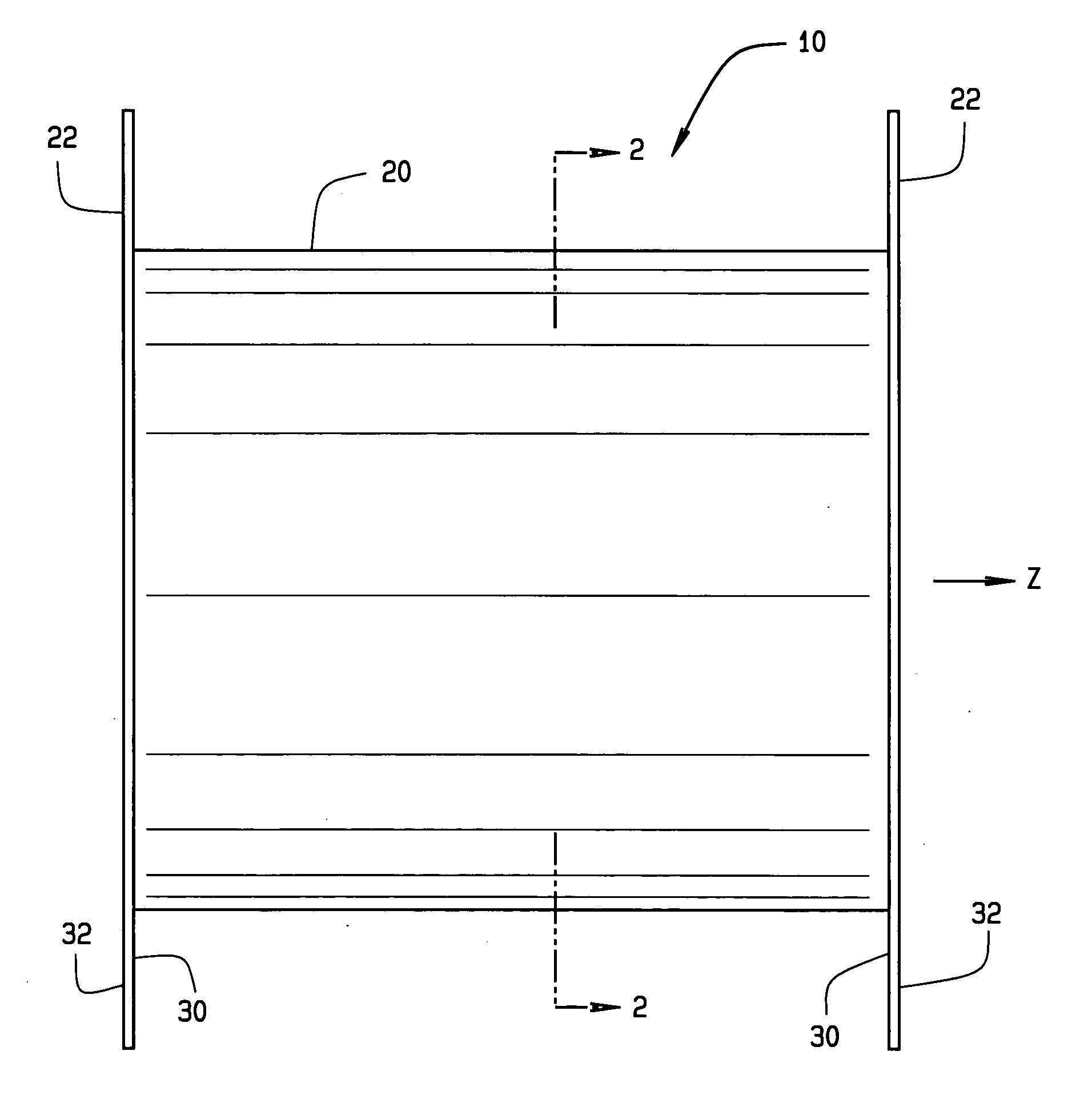
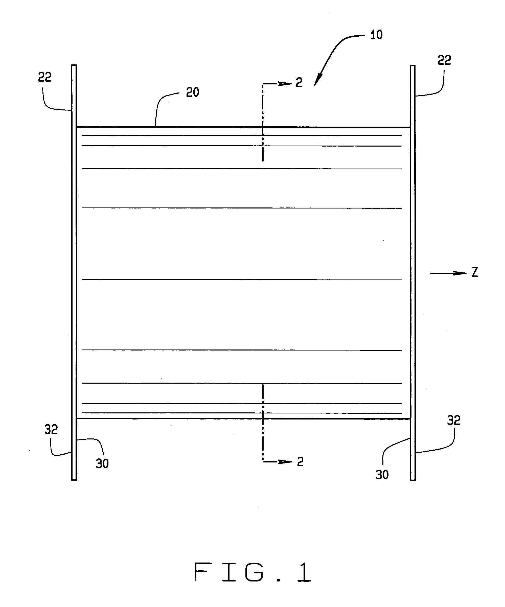
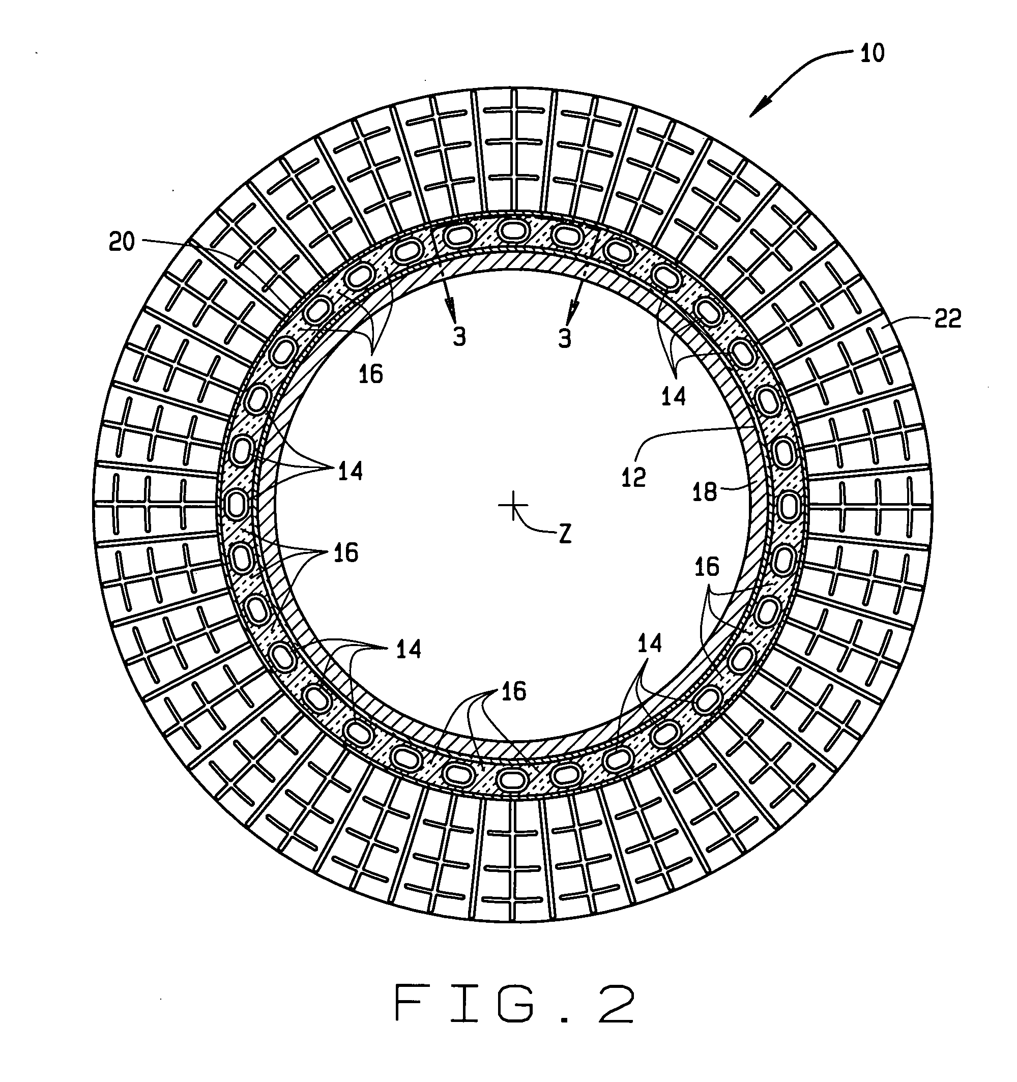
[0016] In some configurations of the present invention and referring to FIGS. 1 and 2, an electrical component 10 includes a thermally conductive, non-magnetic spreader substrate 12. At least one serpentine cooling tube 14 is disposed on and is in thermal contact with at least one of the thermally conductive surfaces of substrate 12, for example, the outside surface of substrate 12.

[0017] In some configurations, cooling tubes 14 have coolant running through them and exchange heat with a remote heat exchanger. Suitable coolants include, but are not limited to, water, water and glycol mixtures, refrigerant, or dielectric fluids such as FC-72 or HFE7100. When cooling tube 14 is operating, the outside surface of substrate 12 is cooled. A thermally-conducting filler 16 is applied in some configurations between curves of cooling tube 14. A cylindrical magnetic winding layer 18 is in thermal contact with the inside surface of substrate 12, which conducts heat from winding layer 18 to non-...


PUM


Abstract

In one aspect, the present invention is a cooling assembly for an electrical component. The assembly includes a non-magnetic, thermally conducting spreader substrate, and at least one serpentine cooling tube disposed on and in thermal contact with the thermally conducting spreader substrate so that said substrate is cooled when the one or more serpentine cooling tubes are operating.

Description

BACKGROUND OF THE INVENTION [0001] This invention relates generally to apparatus for thermal management of heat-generating electrical components and devices using such apparatus, including but not limited to thermally managed gradient coils in magnetic resonance imaging (MRI) systems, and MRI systems using such thermally managed electrical components. [0002] A highly uniform magnetic field is useful for using magnetic resonance image (MRI) and nuclear magnetic resonance (NMR) systems as a medical device or a chemical / biological device. Popular and low maintenance cost MRI systems currently available use a permanent magnet system that creates a middle to high range uniform field in a pre-determined space (imaging volume). A permanent magnet system usually uses multiple permanent magnet blocks such as NdFeB to form a single magnetic object and to achieve a desired high uniform magnetic field in the imaging volume. In other known systems, an electromagnetic coil (such as a superconduct...

Claims


Application Information

Patent Timeline
IPC IPC(8): G01R33/389A61B5/055G01R33/38G01R33/385H05K7/20
CPCG01R33/3856G01R33/3804
Inventor ARIK, MEHMETROHLING, KENNETH WILLIAMWATKINS, RONALD DEAN
Owner GE MEDICAL SYST GLOBAL TECH CO LLC
Why Eureka
Try Eureka