Semiconductor integrated circuit
a technology of integrated circuits and semiconductors, applied in the field of semiconductor integrated circuits, to achieve the effects of preventing data retention loss, efficient operation of refresh timers, and reducing standby curren
- Summary
- Abstract
- Description
- Claims
- Application Information
AI Technical Summary
Benefits of technology
Problems solved by technology
Method used
Image
Examples
first embodiment
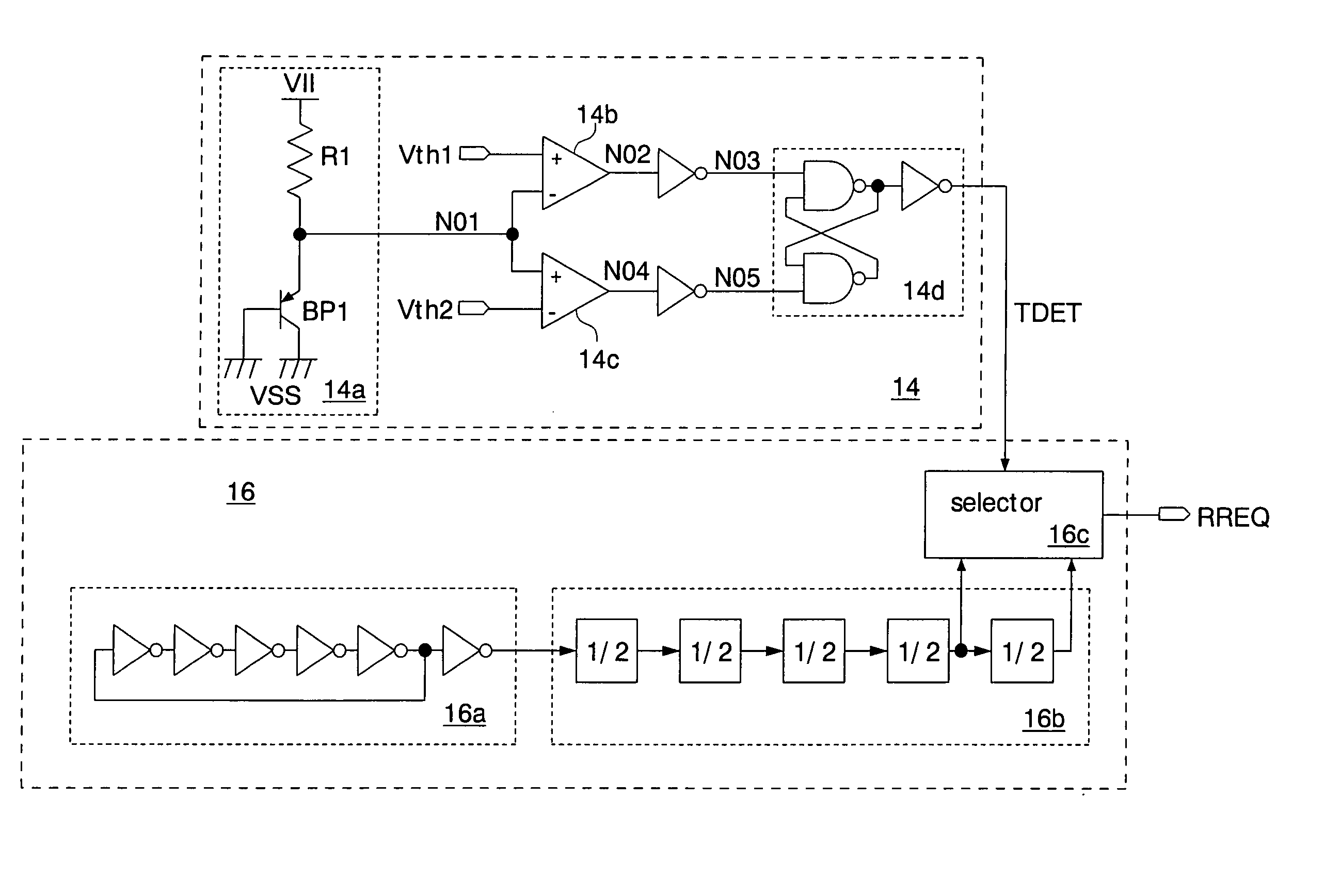
[0062]FIG. 4 shows the semiconductor integrated circuit of the present invention. This semiconductor integrated circuit is formed on a silicon substrate as a pseudo SRAM, using a CMOS process. The pseudo SRAM has a memory core of a DRAM and an interface of an SRAM. The pseudo SRAM executes a refresh operation periodically inside a chip without receiving an external refresh command and retains data written to memory cells. The pseudo SRAM is used as a work memory mounted on, for example, a cellular phone. A read operation and a write operation are executed in response to command signals CMD (a read command signal and a write command signal) supplied via an external terminal.
[0063] The pseudo SRAM has a command input circuit 10, a reference voltage generator 12, a temperature detector 14, a refresh timer 16, a refresh address generator 18, an address input circuit 20, a data input / output circuit 22, an operation control circuit 24, an address switching circuit 26, and a memory core 28...
second embodiment
[0106] The reference voltage setting circuit 42 outputs 8-bit setting signals SET in order to initially set respective values of the threshold voltages Vth1-4 to be generated by the reference voltage generator 36. 2 bits of the setting signals SET are used to make the initial setting of each of the threshold voltages Vth1-4. The logic of the setting signals SET is fixed during manufacturing processes of the pseudo SRAM as in the
[0107]FIG. 13 shows the temperature detector 38 shown in FIG. 12 in detail. A temperature detecting unit 14a, differential amplifiers 14b, 14c, and a flipflop 14d for generating the temperature detecting signal TDET1 are the same as those in the temperature detector 14 (FIG. 5) of the first embodiment. Further, the temperature detector 38 has differential amplifiers 38b, 38c and a flipflop 38d for generating the temperature detecting signal TDET2.
[0108] An output (a detection voltage N31) of the temperature detecting unit 14a is inputted in common to the dif...
sixth embodiment
[0137] The reference voltage generator 58 has a resistor array 54e in place of the resistor array 54d of the The other configuration is the same as the logical configuration of the reference voltage generator 54 of the six embodiment. The resistor array 54e has four resistors connected in series. A threshold voltage Vth1 (or Vth2, Vth3, Vth4) is generated from a connecting node of two adjacent resistors.
[0138] The same effects as those of the above-described first, second, fourth, and sixth embodiments are also obtainable in this embodiment.
[0139]FIG. 20 shows an eighth embodiment of the semiconductor integrated circuit of the present invention. The same reference numerals and symbols are used to designate the same elements as the elements explained in the first and fifth embodiments, and detailed explanation thereof will be omitted. The semiconductor integrated circuit of this embodiment is formed on a silicon substrate as a DRAM having a self-refresh function, using a CMOS proce...
PUM
 Abstract
Description
Claims
Application Information
 - R&D
- Intellectual Property
- Life Sciences
- Materials
- Tech Scout
- Unparalleled Data Quality
- Higher Quality Content
- 60% Fewer Hallucinations
Browse by: Latest US Patents, China's latest patents, Technical Efficacy Thesaurus, Application Domain, Technology Topic, Popular Technical Reports.
© 2025 PatSnap. All rights reserved.Legal|Privacy policy|Modern Slavery Act Transparency Statement|Sitemap|About US| Contact US: help@patsnap.com


