Magnetic thin film, magnetic component that uses this magnetic thin film, manufacturing methods for the same, and a power conversion device

a technology of magnetic thin film and magnetic component, which is applied in the field of magnetic thin film, can solve the problems of difficult control of the film thickness of the magnetic thin film, difficult to obtain a good magnetic quality, and difficult to form a magnetic thin film on top of a semiconductor substrate, etc., and achieves the effect of soft magnetic qualities and easy manufacturing

Inactive Publication Date: 2005-05-05
FUJI ELECTRIC DEVICE TECH CO
View PDF18 Cites 29 Cited by
  • Summary
  • Abstract
  • Description
  • Claims
  • Application Information

AI Technical Summary

Benefits of technology

[0018] It is an object of the present invention is to provide a magnetic thin film that is well suited for mass production, can be manufactured easily, can be made into a thick film, has soft m

Problems solved by technology

As a result, it is difficult to form a magnetic thin film on top of a semiconductor substrate which has a built-in IC (integrated circuit) and the like.
Furthermore, when using plating, although manufacture by normal temperature treatment is possible, the control of the film thickness of the magnetic thin film is difficult.
As a result, it is difficult to obtain a good magnetic quality.
However, the manufacture process is complex, and mass production is difficult.
Therefore, the manufacture cost of magnetic components using this magnetic thin film is high.
Furthermore, because the speed of growth is slow with the sputter method, making a thick film is difficult.
Even if mass production is not considered, if the thickness is made any greater, there can be cracking and loss due to membrane stress.
However, with magnetic thin films formed in this manner, because a sputter method is used, the manufacturing costs are high, and making a thick film is difficult.
In responding to this demand, this bulky transformer of the prior art has been a large bottleneck.
The interlinkage flux between the primary and secondary coils is reduced, and as a result, the magnetic bond between them is weakened, and the output from the

Method used


Image

  • Magnetic thin film, magnetic component that uses this magnetic thin film, manufacturing methods for the same, and a power conversion device
  • Magnetic thin film, magnetic component that uses this magnetic thin film, manufacturing methods for the same, and a power conversion device
  • Magnetic thin film, magnetic component that uses this magnetic thin film, manufacturing methods for the same, and a power conversion device

Examples


first embodiment

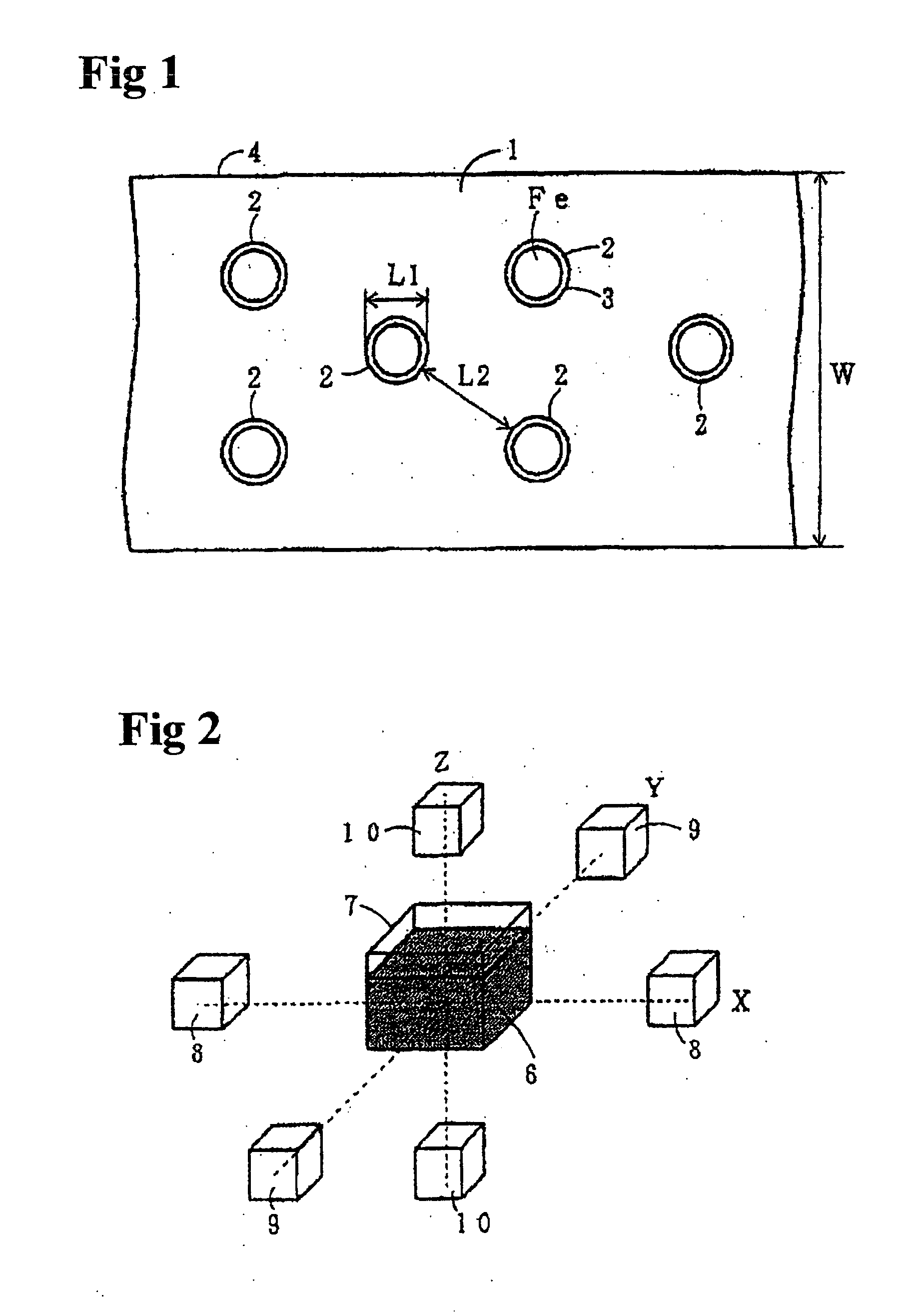
[0163] Referring to FIG. 1, there is a cross-section of the principal part of the magnetic thin film of the present invention. A magnetic particle 2 of size 20 nm is formed by surrounding Fe fine particles with a thin oxide film 3 of a thickness of several nm's. A magnetic thin film 4 has a structure in which magnetic particles 2 are scattered in a polyimide film 1 at approximately 100 nm intervals. Stated differently, magnetic thin film 4 has a structure wherein entities (the aforementioned cells) in which magnetic particles of 20 nm is surrounded by polyimide of approximately 100 nm thickness are placed approximately uniformly in polyimide. Furthermore, in terms of manufacturing the magnetic component, the practicable range for thickness W of magnetic thin film 4 is from several μm to several 10's of μm. If the thickness is less than several μm, it is difficult to achieve a magnetic flux density that is necessary for a magnetic component. As a magnetic component, adequate magnetic...

fourth embodiment

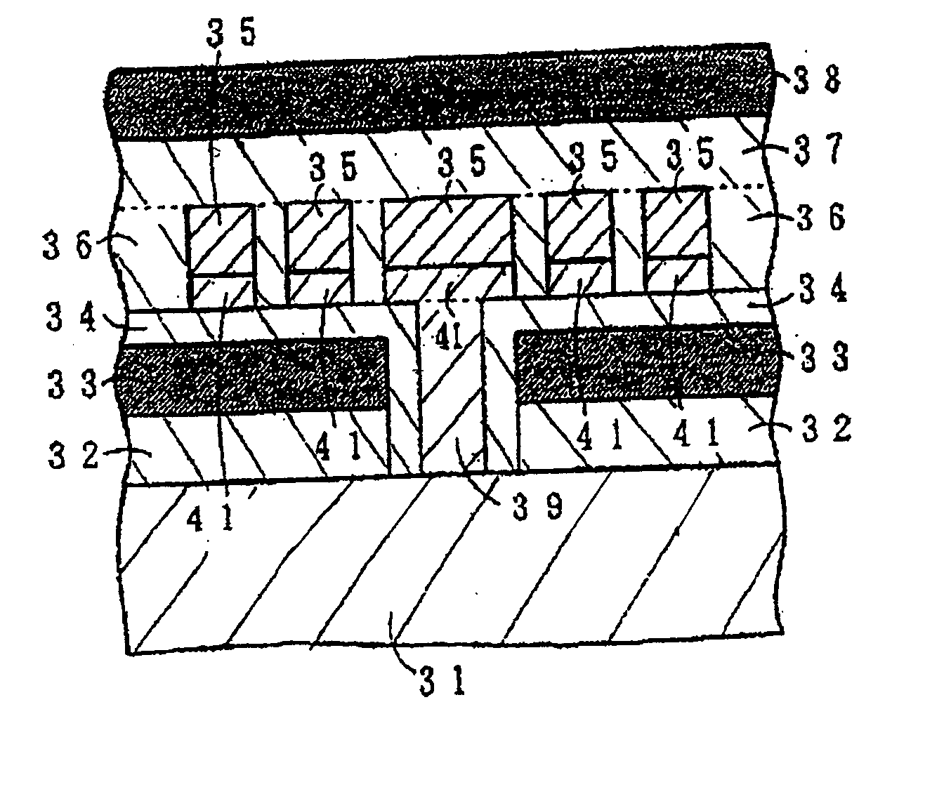
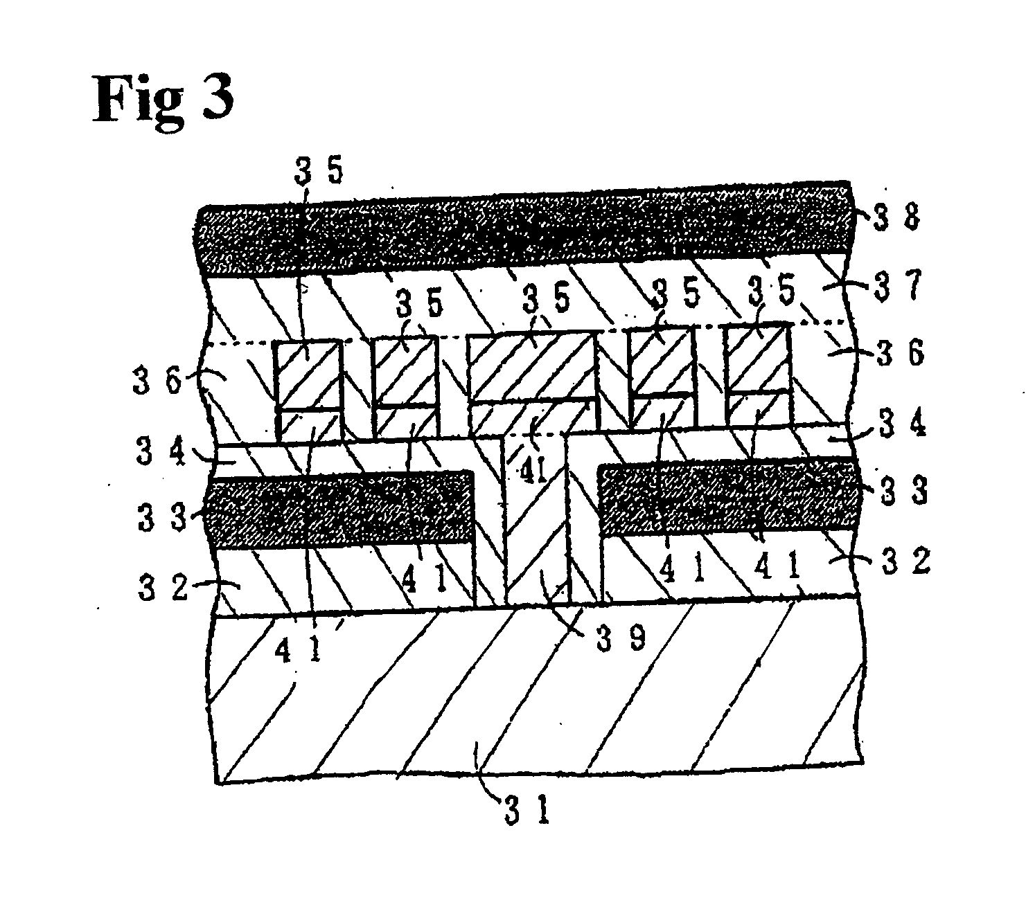
[0179] Polyimide film 62 is formed on top of silicon substrate 61 with a built-in semiconductor element. In the same manner as in the fourth embodiment, Fe particles that have their surfaces covered with an oxide and that have a particle size of 20 nm are dispersed in a non-photosensitive polyimide. This is rotation coated at a rotation frequency of 500 rpm and baked. Magnetic thin film 63 of thickness 20 μm is formed on top of polyimide film 62. On top of magnetic thin film 63, in the same manner as in the prior art, a plating electrode of Ti / Au film 64 and Ti / Au connection conductor 69 are formed (FIG. 6(a)). Next, photosensitive polyimide in which magnetic particles are dispersed is rotation coated at a rotation frequency of 200 rpm and baked. This is exposed to light and developed, and plating mask 65 with a thickness of 30 μm is formed. As with the prior art, Cu coil 66 with a thickness of 30 μm and a turn number of 16 is formed (FIG. 6(b)). Again, on top of this, non-photosens...

seventh embodiment

[0180] Referring to FIG. 7, a cross-section diagram of the principal parts of a thin film inductor of the present invention is shown.

[0181] A polyimide film 72 is formed on top of a silicon substrate 71 in which a semiconductor element is built in. On top of polyimide film 72, a magnetic thin film 73 with a thickness of 10 μm is formed. With magnetic thin film 73, Fe fine particles that are covered with an oxide film and that have an average particle size of 20 nm are aggregated as in FIG. 13. On top of magnetic thin film 73, a plating electrode of a Ti / Au film 74 and a connection conductor 79 which connects with silicon substrate 71 are formed. On top of this, a Cu coil 76 of thickness 30 μm and 16 turns is formed. A magnetic thin film 78 in which Fe fine particles are aggregated is formed between and above Cu coil 76, and the thin film inductor is completed. Compared with the third and fifth embodiments, the magnetic bonding is strong because there is no resin (however, because fi...


PUM


Abstract

On top of a silicon substrate, a polyimide film with a thickness of 10 μm is formed. On top of this, a magnetic thin film that is a polyimide film containing Fe fine particles and that has a thickness of 20 μm is formed. On top of this magnetic thin film, a patterned Ti/Au film and a Ti/Au connection conductor are formed. On top of this, a polyimide film with a thickness of 10 μm, and a Cu coil with a height 35 μm, width 90 μm, space 25 μm, and a polyimide layer that fills the spaces in the Cu coil are formed. On top of this, via a polyimide film with a thickness of 10 μm, a magnetic thin film that is a polyimide film containing Fe particles and that has a thickness of 20 μm is formed. This thin film inductor has a small alternating current resistance. The present invention provides a magnetic thin film that is well suited for mass production, can be manufactured easily, can be made into a thick film, has soft magnetic qualities, and is inexpensive. The present invention also provides a magnetic component that uses this magnetic thin film, manufacturing methods for these, and a power conversion device.

Description

BACKGROUND OF THE INVENTION [0001] The present invention relates to a magnetic thin film that can act as a magnetic core for a magnetic component such as a reactor, transformer, and magnetic head and the like. The present invention also relates to a magnetic component in which this magnetic thin film is formed on top of a semiconductor substrate. The present invention also relates to their manufacturing methods. The present invention also relates to a power conversion device. [0002] In the prior art, the magnetic thin film that is the magnetic core of magnetic components such as reactors, transformers, and magnetic heads, and the like is generally manufactured by methods such as sintering, rolling, plating, and sputtering of magnetic materials. [0003] Depending on the usage of the magnetic component, different magnetic qualities are needed. As a general classification, there are hard magnetic qualities and soft magnetic qualities. In hard magnetic qualities, the B-H quality has an a...

Claims


Application Information

Patent Timeline
IPC IPC(8): G11B5/31G11B5/37H01F1/00H01F10/00H01F10/32H01F17/00H01F41/16H01L23/31H01L23/522H01L23/64
CPCB82Y25/00G11B5/3109H01L2924/01015H01L2224/45147H01L2924/01068G11B5/37H01F1/0027H01F10/005H01F10/007H01F10/3254H01F17/0006H01F41/16H01F2017/0066H01L23/3128H01L23/3135H01L23/5227H01L23/552H01L23/645H01L2224/48227H01L2224/48247H01L2924/01012H01L2924/01025H01L2924/01039H01L2924/01078H01L2924/01079H01L2924/15311H01L2924/19041H01L2924/19104H01L2924/30107H01L2924/3025H01L24/48H01L2924/00H01L24/45H01L2224/45015H01L2224/451H01L2924/14H01L2924/181H01L2924/00014H01L2924/00015H01L2924/00012
Inventor MATSUZAKI, KAZUOFURUTA, TAKUTAKAGIWA, KAZUMIHAYASHI, ZENCHI
Owner FUJI ELECTRIC DEVICE TECH CO
Why Eureka
Try Eureka