These sites are chosen for convenience rather than
correctness, due to there exist many factors to influence the accuracy, such as: unsteady and unsuitable placement of
thermometer probe in the measuring site, drinking, talking, inexperienced measuring skill, etc.
However, there exists some drawback on using the infrared ear thermometer for getting the body temperature, such as:
As the probe tip
diameter is equal or even a little bit bigger than the normal adult's and especially the children's
ear canal's regular
diameter, when inserting the probe head into the
ear canal, the
close contact between the ear thermometer probe and the
ear canal's internal
skin wall will cause a rapid heat increase on the probe and result in a temperature rising on the infrared sensor's cold junction.
This prevents from getting a stable or accurate temperature reading display.
Moreover, the innate curvature structure inside the ear canal will make the probe inconsistently to be inserted into the ear canal for getting a consistent reading.
There are still some more usage concerns when using
ear thermometers: The earwax may result in an inaccurate reading, the curvature structure inside the ear canal may cause an inconsistent measuring result due to the inappropriate probe positioning in the ear canal, the inconvenience and cost consuming concern for the necessity to put on the probe covers, the unreliable measurement reading display caused by the poor heat insulation design of the probe
assembly, the disturbance to the sleeping patient (specially the infant or children) during the temperature measuring, the cool effect and low read concern from continuous measuring with repeated probe
insertion into the ear canal within a short period of time, and the inapplicability for the bigger probe to be inserted into patient's ear, especially the concern of smaller ear
diameter for children under aged two or even neonates.
These proposals, have, however, some drawbacks.
The problem of contact with the ear canal is thus not solved.
Firstly, relatively complicated calculations are proposed for adjustment of the temperature which requires powerful calculating arrangements.
Secondly, the problem of contact with the ear canal is not addressed.
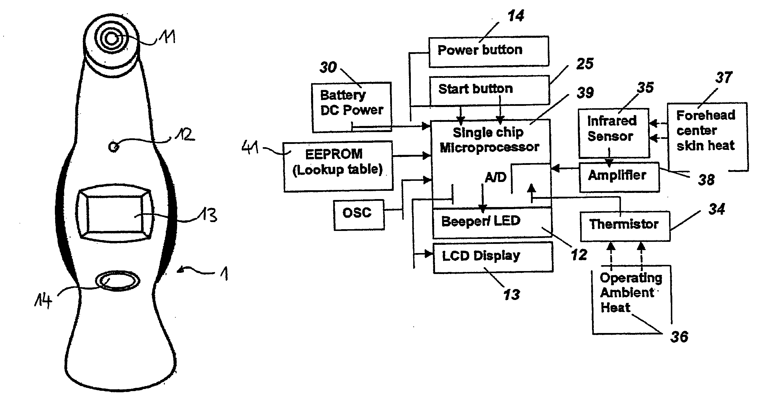
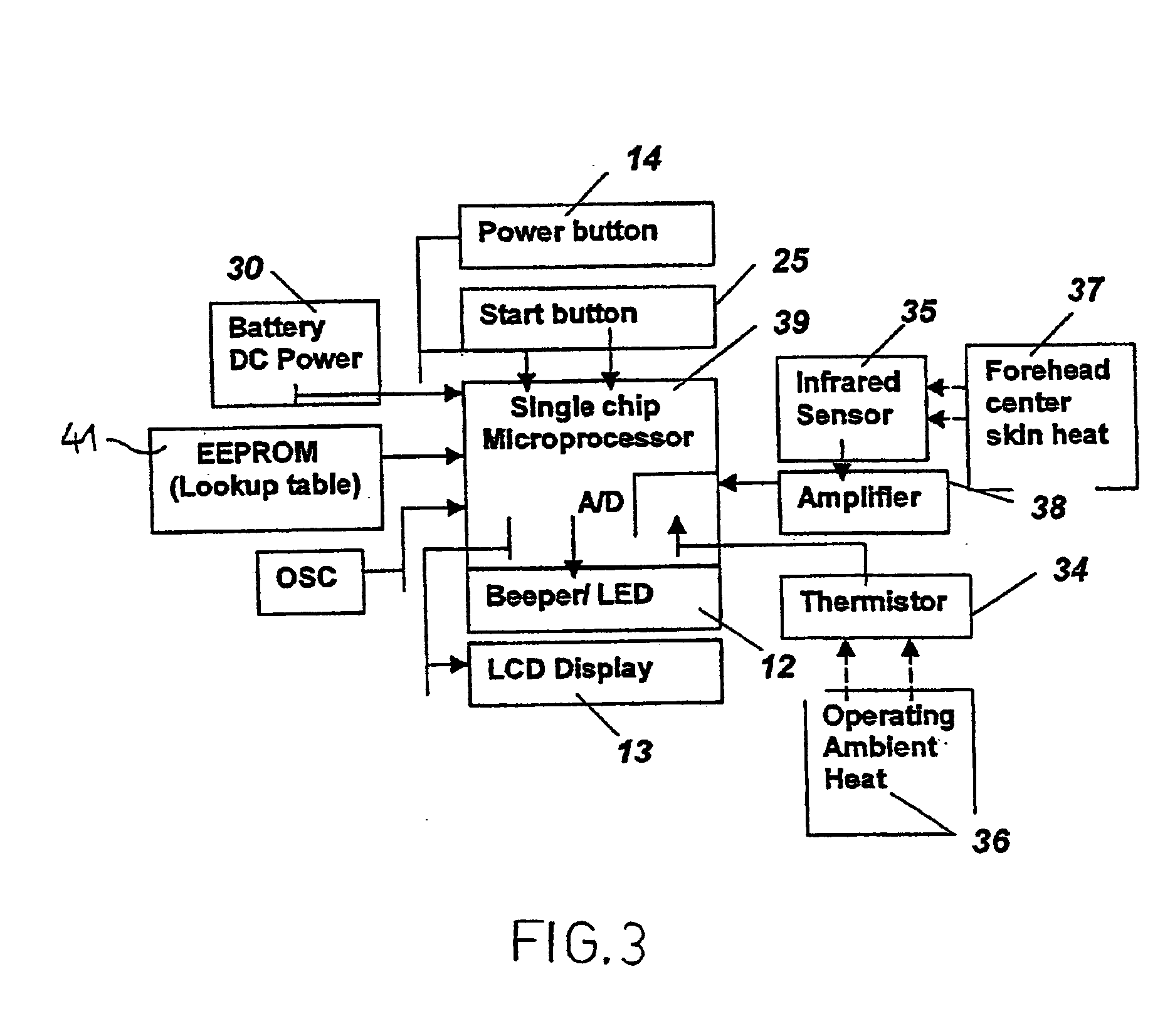
Thirdly, by measuring the ambient temperature, inaccurate measurement results may be created if there is a difference between the cold junction of a
thermopile of the
infrared detector and the ambient temperature.
None of these documents completely solves the above mentioned problems, namely problems associated with contact of a temperature sensor with an ear canal as well as problems related to relatively complicated prior art calculations for determining a temperature of a first body site in dependence of the measurement at another body site.
It is directed e.g. to a tympanic thermometer which does not solve the problem of contact between the sensor and the ear canal.

