Wearable biomonitor with flexible thinned integrated circuit

a biomonitor and integrated circuit technology, applied in the direction of instruments, diagnostic recording/measuring, force/torque/work measurement apparatus, etc., can solve the problems of system noise of the past, and achieve the effect of avoiding noise, low profile and more nois

Inactive Publication Date: 2005-05-05
IRVINE SENSORS
View PDF19 Cites 252 Cited by
  • Summary
  • Abstract
  • Description
  • Claims
  • Application Information

AI Technical Summary

Benefits of technology

[0007] The sensor module can be made in appearance similar to an adhesive bandage and can be analogously adhered to the skin of a subject body in a convenient manner. The sensor module has no wires or cords extending to monitoring/receiving equipment. Therefore, there are no encumbering lines to entangle the limbs and torso of a subject body being monitored. As such, the subject body is free to walk and move about without interrupting the monitoring process, and without the sensor system or module interrupting the normal activities of the subject body. In this way, the subject person's bodily characteristics that are being monitored are closer to, if not the same as, what they would be during regular activities. Thus, the characteristics being monitored will more accurately reflect those characteristics that the subject body normally has, and will record the physiological responses of the subject body to his or her normal environment.
[0008] In this way the instant invention to be monitored outside the unnatural environment of a clinic or hospital or to be monitored more conveniently in such an environment. The bio-sensor system of the instant invention permits a subject person to not only be at home or work, but also...

Problems solved by technology

The systems of the past have more noise because they have longer circuit paths between the monitoring circuitry and the physiological interface elements and longer circuit paths between the monitoring circuitry and the noise creating power supplies.
In other words, the instant...

Method used


Image

  • Wearable biomonitor with flexible thinned integrated circuit
  • Wearable biomonitor with flexible thinned integrated circuit
  • Wearable biomonitor with flexible thinned integrated circuit

Examples


Embodiment Construction

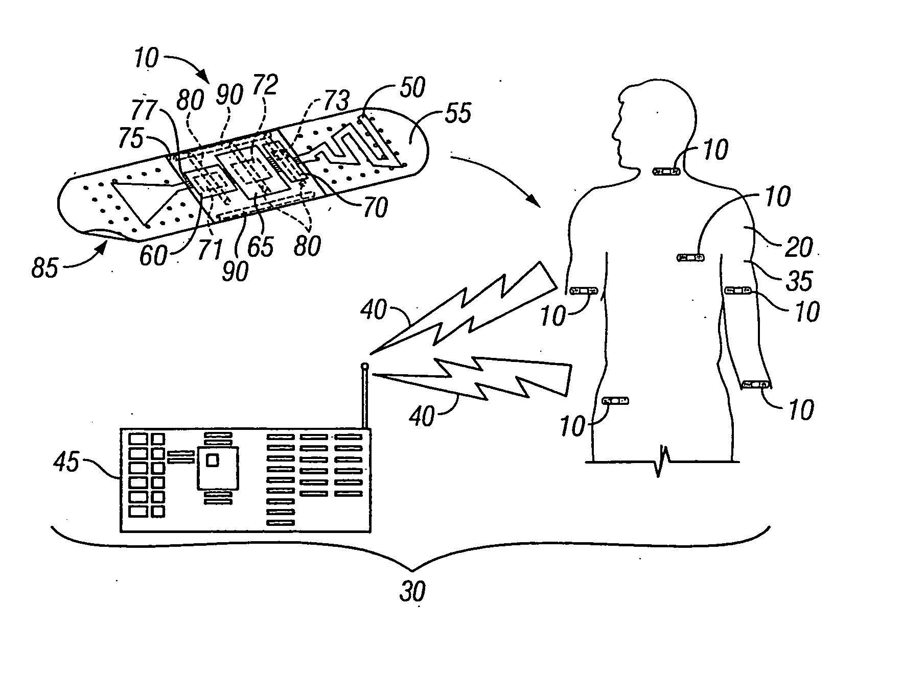
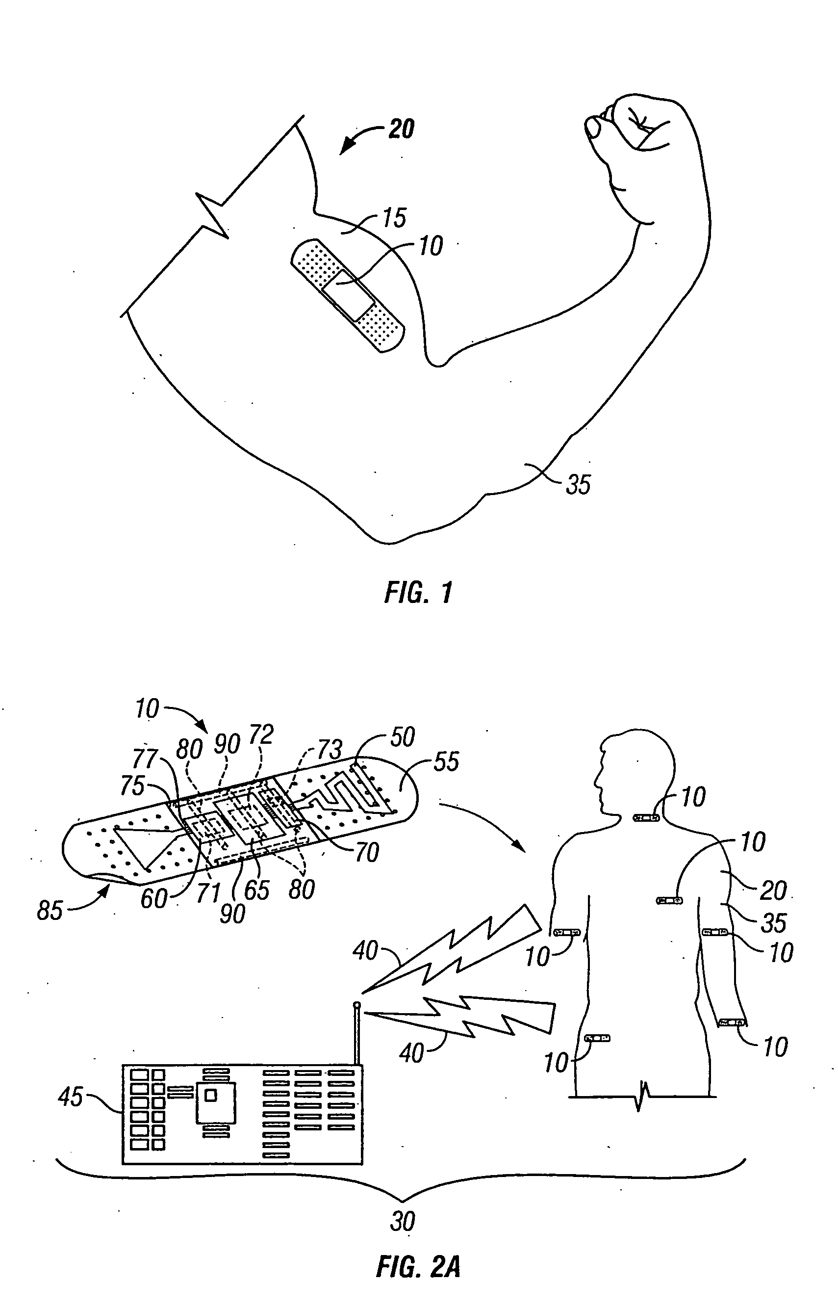
[0038]FIG. 1 shows an exemplary preferred embodiment of a sensor module 10 adhered to the skin 15 of a subject body 20 to be monitored. The sensor module 10 can be a single sensor module, (or one of a plurality of sensor modules), of the sensor system 30 shown in FIG. 2a in accordance with a preferred embodiment of the invention. As can be appreciated from FIG. 1, the sensor module 10 is completely unobtrusive, is self-contained, and is void of the monitor wires and other encumbrances that have conventionally entangled arms 35 and other parts of the subject body 20 during monitoring.

[0039] As shown in FIG. 2a, the system 30 can incorporate continuous transmission by RF signals 40 to a device 45 having a receiver, data storage, and / or means for analyzing the data. In this case, the sensor module 10 has at least one antenna 50 metalized onto a flexible substrate 55 for transmitting and / or receiving RF signals. As shown in FIG. 2a, thin flexible silicon substrates 60, 65, 70 havin...


PUM


Abstract

A sensor system (30) has a sensor module (10) and a receiver module (45). The sensor module (10) functions as a wireless data collection device and has a flexible thin sheet of silicon (60, 65, 70) comprising circuitry (71, 72, 73), a flexible power source (105), and a flexible support substrate (55). The silicon, power source, and flexible support substrate are integrated as layers of the sensor module (10). The layers are placed together in the form of an adhesive bandage (10). A plurality of electrodes (80) are connected to the sensor module (10) and protrude from the flexible substrate (55) for contacting the skin of a subject body (20). The receiver module (45) includes one of an RF receiver with a wireless port for continuously receiving data (40), or a physical I/O port (87) to which the sensor module (10) can be physically connected for downloading stored data from the sensor module (10).

Description

CROSS REFERENCE TO APPLICATIONS [0001] This application is a continuation-in-part of U.S. patent application Ser. No. 09 / 190,378 filed Nov. 10, 1998, entitled “Method for Thinning Semiconductor Wafers with Circuits and Wafers Made by the Same”, which claims the benefit of provisional application Ser. No. 60 / 065,088, filed Nov. 11, 1997, entitled “Method for Thinning Semiconductor Wafers with Circuits” and this application claims the benefit of U.S. patent application Ser. No. 60 / 305,353 filed Jul. 16, 2001, entitled “Biomonitor Device”, all three of which are incorporated herein by reference.BACKGROUND OF THE INVENTION [0002] 1. Field of the Invention [0003] The instant invention relates generally to sensor systems for detecting physiological characteristics, and more specifically to a sensor system comprising a thin flexible ambulatory / self contained bio-sensor module in a form similar to an adhesive bandage for sensing physiologically modulated signals from the body, and a method ...

Claims


Application Information

Patent Timeline
IPC IPC(8): H01L21/68
CPCA61B2562/164H01L2221/68327H01L21/6836
Inventor OZGUZ, VOLKAN H.KHASHAYAR, ABBAS
Owner IRVINE SENSORS
Why Eureka
Try Eureka