Apparatus and method for retrograde placement of sagittal sinus drainage catheter

Active Publication Date: 2005-05-05
MEDTRONIC INC
View PDF15 Cites 22 Cited by
  • Summary
  • Abstract
  • Description
  • Claims
  • Application Information

AI Technical Summary

Benefits of technology

[0016] In another embodiment, the present invention provides a sagittal sinus catheter adapted for placement into said cranium of said patient proximate a superior sagittal sinus. The catheter is formed of a semi-rigid material. The catheter has at least a ninety degree bend aiding insertion in the retrograde direction and limiting the depth of insertion.
[0017] Positioning the discharge end of the sinus catheter in the retrograde facing the upstream flow of blood in the sa

Problems solved by technology

However, if blockages in circulation of CSF, perhaps in the ventricles, CSF can't be reabsorbed by the body at the proper rate.
If left untreated, the increased intracranial pressure can lead to neurological damage and may result in death.
Differences in pressure due, at least in part, to differences in vertical position between the inlet (ventricles) and the outlet (peritoneum) can create too much drainage with such a flow or pressure regulating valve.
However, controlling the length of the slit in the dura is difficult and will vary from surgery to surgery.
Still, controlling the shape and diameter of the opening in the dura is difficult and, again, will vary fr

Method used


Image

  • Apparatus and method for retrograde placement of sagittal sinus drainage catheter
  • Apparatus and method for retrograde placement of sagittal sinus drainage catheter
  • Apparatus and method for retrograde placement of sagittal sinus drainage catheter

Examples


Example

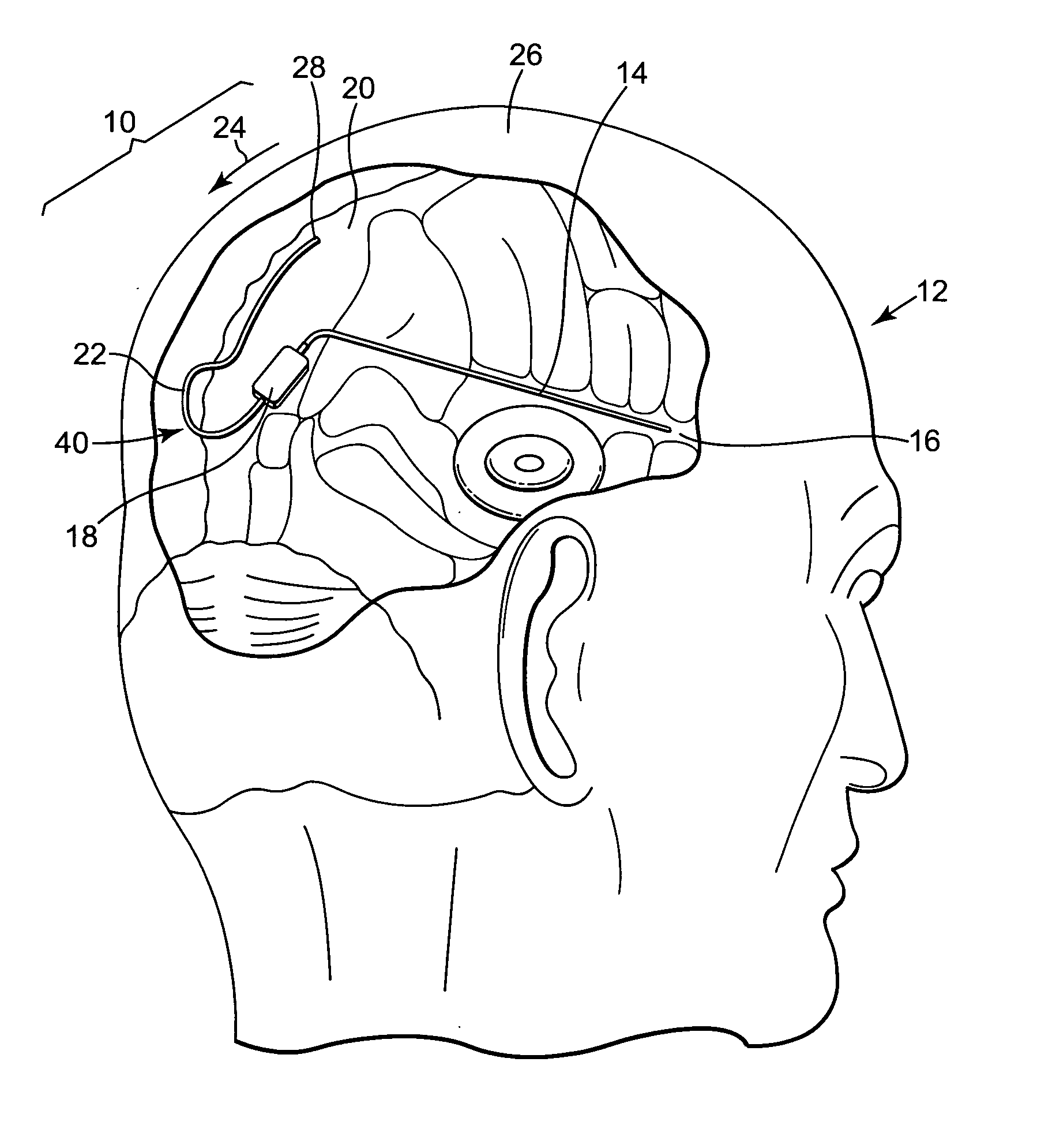
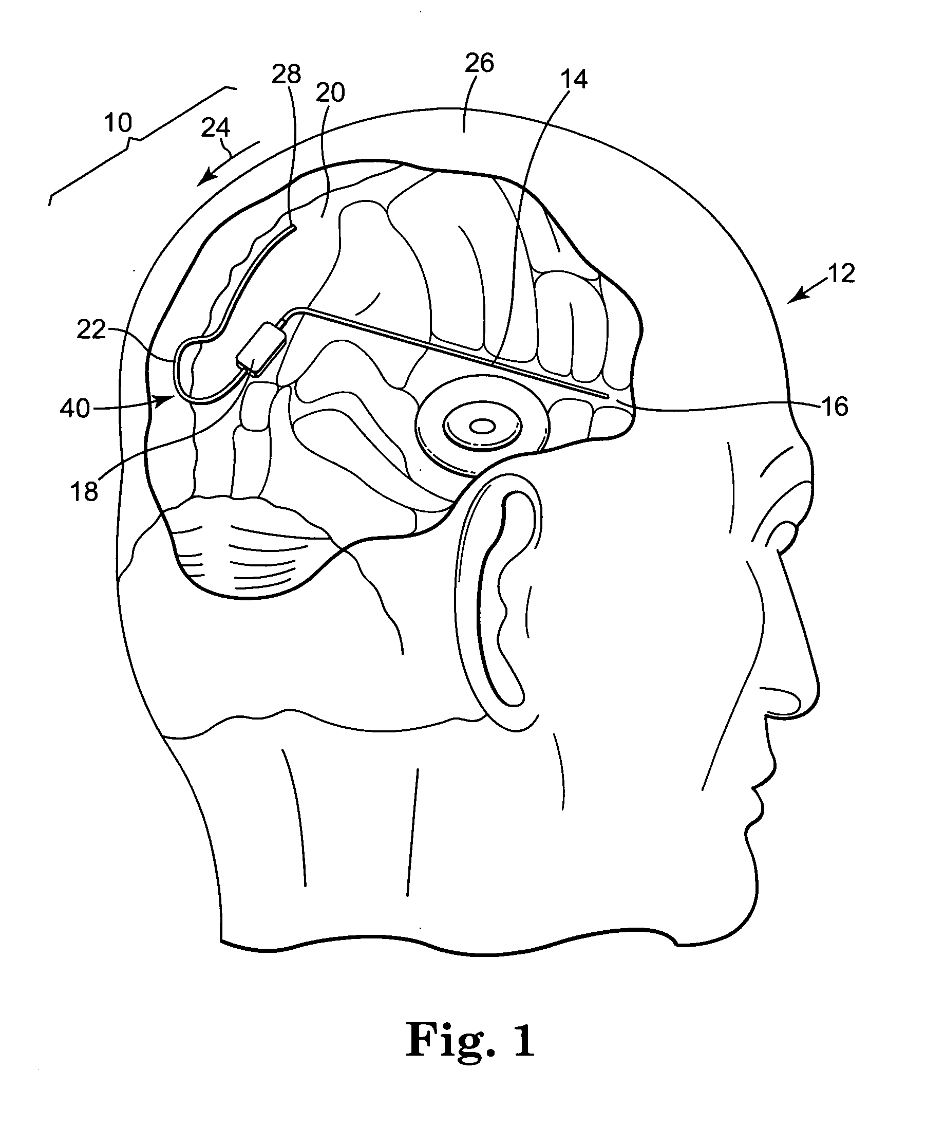
[0030] The various embodiments of the present invention can be understood by reference to the shunt system 10 illustrated in FIG. 1 which shows the ventricular to sagittal sinus shunt system 10 in place in a patient 12. Ventricular catheter 14 has been inserted through a burr hole (not shown) into the lateral ventricle 16 of patient 12. Ventricular catheter 14 is coupled to valve 18 which controls the flow of CSF from lateral ventricle 16 to sagittal sinus 20. Valve 18 is also coupled to sinus catheter 22 shown inserted through another burr hole (also not shown) into the superior sagittal sinus 20.

[0031] Shunt system 10 allows excess CSF present in lateral ventricle 16 to flow through ventricular catheter 14, valve 18 and sinus catheter 22 into the blood stream of sagittal sinus 20 where the excess CSF can be reabsorbed into the body. The vertical distance between the location of ventricular catheter 14 and sinus catheter 22 is small compared with vertical distance usually associat...


PUM


Abstract

A method of inserting a drainage catheter into a sagittal sinus having blood flow from an upstream to a downstream direction. A burr hole is created, if necessary, in the cranium of the patient proximate the sagittal sinus. A distal end of a catheter is inserted through the burr hole and the dura into the sagittal sinus. The distal end of the catheter is positioned so that the distal end points generally in the upstream direction with respect to the blood flow. A sagittal sinus catheter is adapted for placement through the dura of a patient proximate a superior sagittal sinus. The catheter is formed of semi-rigid material and has at least a ninety degree bend.

Description

FIELD OF THE INVENTION [0001] The present invention relates generally to apparatus and methods for the introduction and placement of cranial catheters and, more particularly, to apparatus and methods for the introduction and placement of sinus catheters. BACKGROUND OF THE INVENTION [0002] Ventricles of the brain contain cerebrospinal fluid (CSF) which cushions the brain against shock. CFS is constantly being secreted and absorbed by the body usually in equilibrium. Cerebrospinal fluid is produced in the ventricles of the brain, where under normal conditions, it is circulated in the subarachnoid space and reabsorbed into the bloodstream, predominantly via the arachnoids villi attached to the superior sagittal sinus. However, if blockages in circulation of CSF, perhaps in the ventricles, CSF can't be reabsorbed by the body at the proper rate. [0003] This can create a condition known as hydrocephalus which is a condition marked by an excessive accumulation of fluid violating the cerebr...

Claims


Application Information

Patent Timeline
IPC IPC(8): A61B17/34A61F2/04A61M5/00A61M25/18A61M27/00A61M39/22
CPCA61B17/3415A61M2025/0079A61M27/006
Inventor MOSKOWITZ, ARILINTULA, LEANNE
Owner MEDTRONIC INC
Why Eureka
Try Eureka