
Lean idle speed control using fuel and ignition timing

a technology of ignition timing and idle speed control, which is applied in the direction of electric control, ignition automatic control, speed sensing governors, etc., can solve the problems of reducing fuel economy, slow engine response, and operating well below the air/fuel ratio lean misfire limit, so as to increase the overall operating time, reduce engine output, and accelerate engine response

Inactive Publication Date: 2005-05-12
FORD GLOBAL TECH LLC
View PDF11 Cites 8 Cited by
  • Summary
  • Abstract
  • Description
  • Claims
  • Application Information

AI Technical Summary

Benefits of technology

The present invention provides a method for controlling a lean burn engine that allows for faster engine response and better fuel economy. The method involves calculating the desired engine speed, operating more lean than a predetermined lean air-fuel ratio to produce an engine output, increasing the engine output to maintain the desired engine speed by operating less lean, and decreasing the engine output to maintain the desired engine speed by operating more lean and retarding ignition timing. By increasing engine output via enriching the air-fuel ratio and decreasing engine output via ignition timing retard, the engine can operate with a smaller margin between the lean operation air-fuel ratio and the lean misfire limit while still providing quick output control action. The method also allows for more efficient fuel economy and better engine performance.

Problems solved by technology

The inventors herein have recognized disadvantages with such a method for engine idle speed control.
First, controlling fuel quantity or timing as the primary control for a lean burn engine system results in operation well below the air / fuel ratio lean misfire limit due to the reserve capacity.
This reserve capacity can result in decreased fuel economy since operation can occur at a lean air / fuel ratio less lean than otherwise may be possible.
Further, engine idle speed control using airflow as the torque control may result in slow engine response.

Method used


Image

  • Lean idle speed control using fuel and ignition timing
  • Lean idle speed control using fuel and ignition timing
  • Lean idle speed control using fuel and ignition timing

Examples


Embodiment Construction

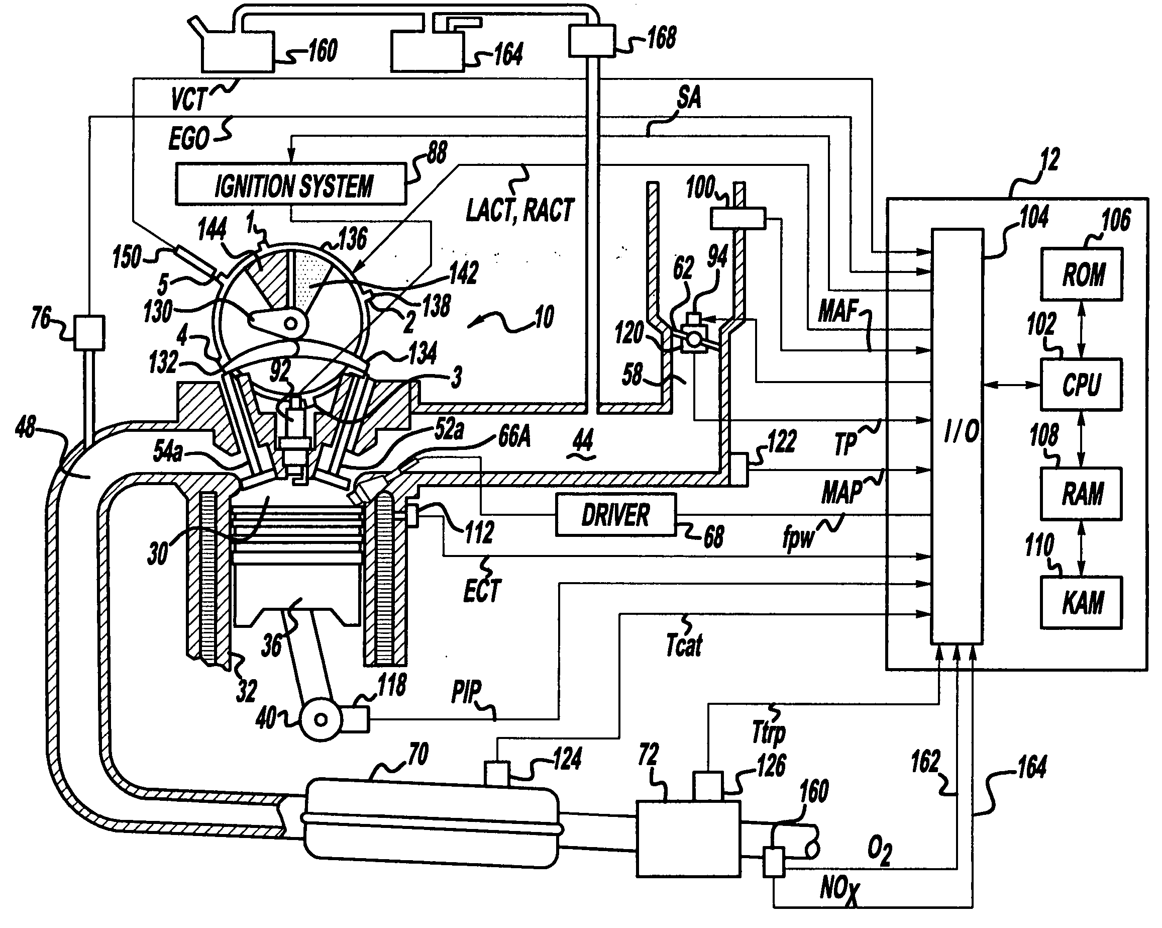
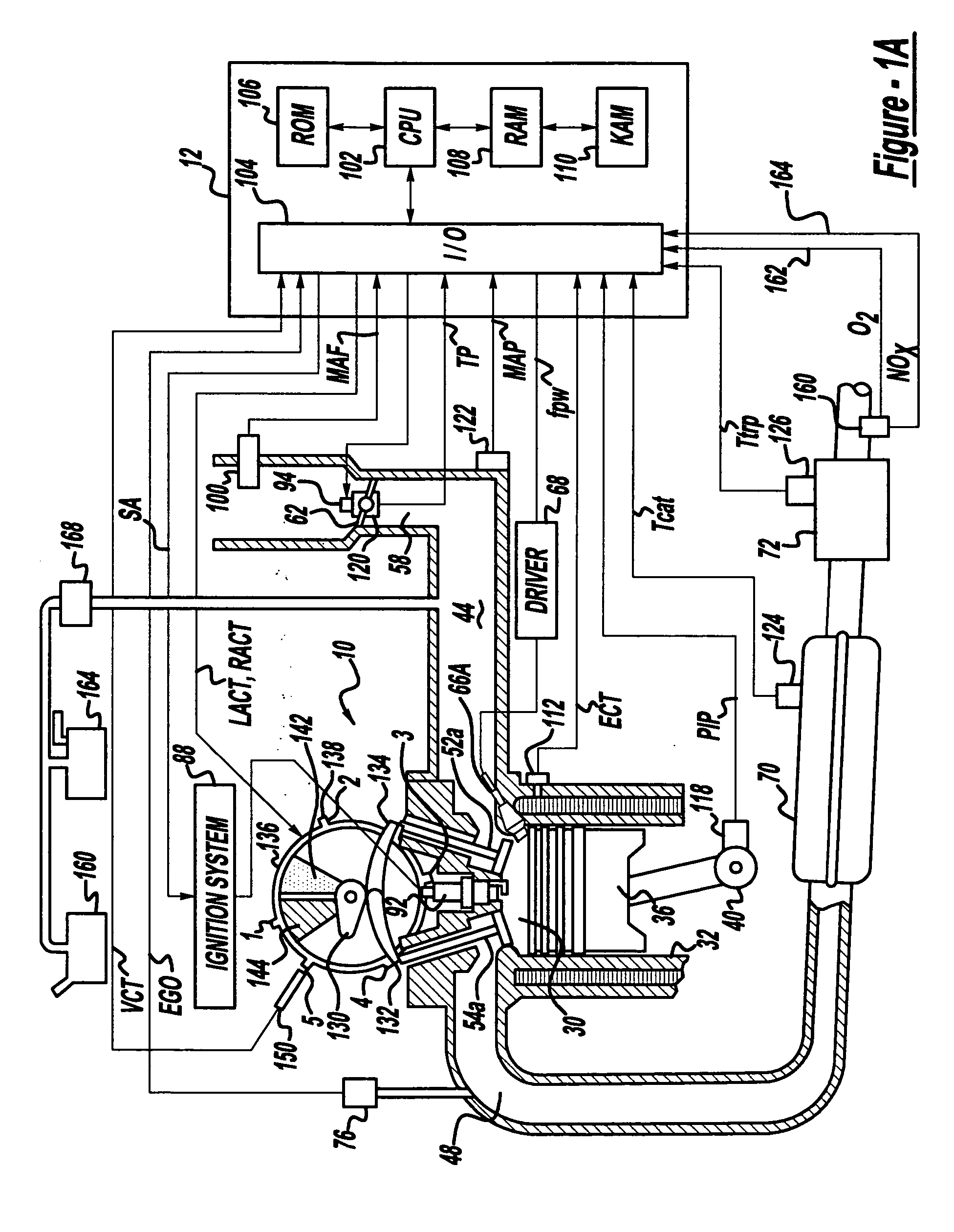
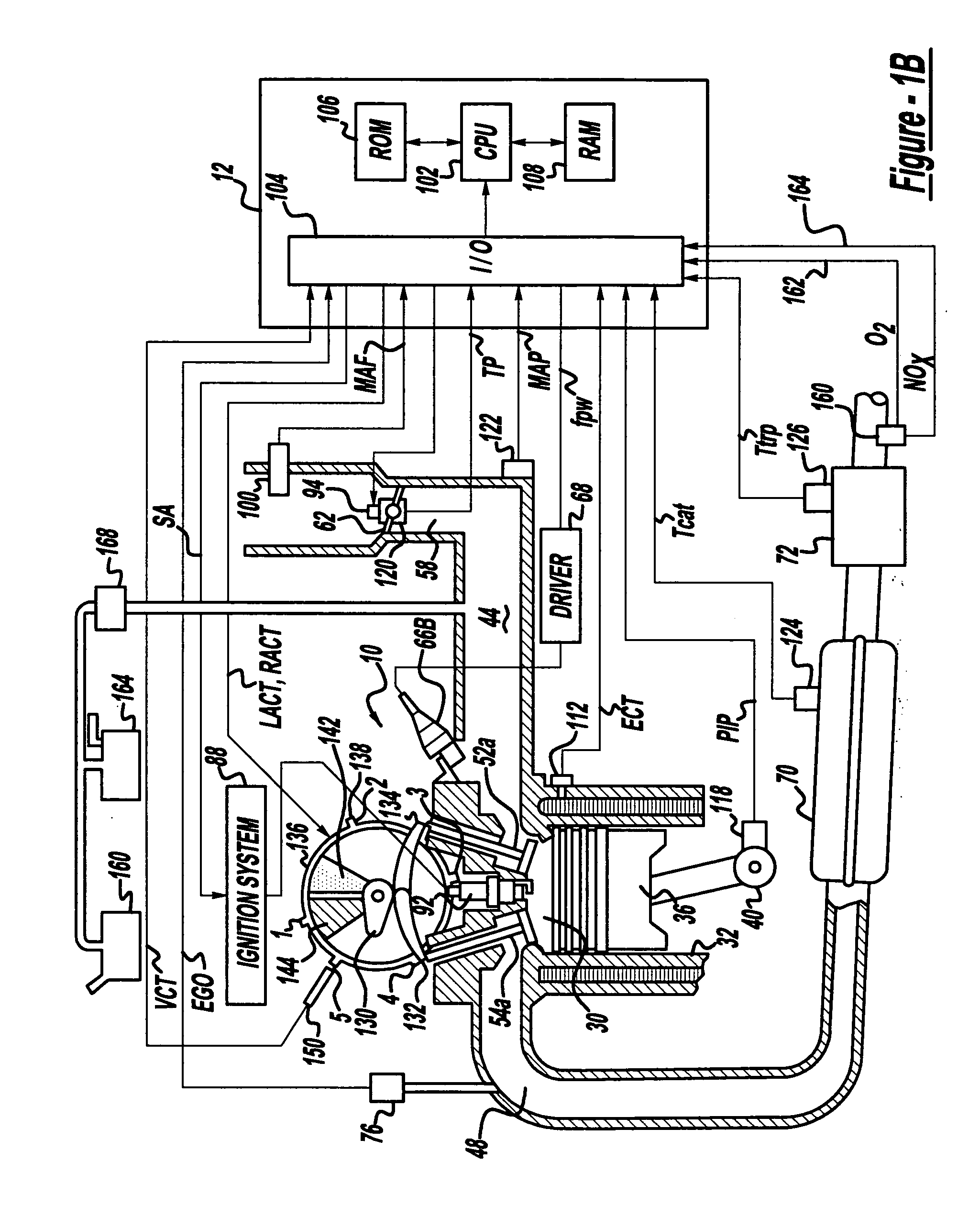
[0016]FIGS. 1A and 1B show one cylinder of a multi-cylinder DISI engine, the intake and exhaust path connected to that cylinder as well as the electronic engine control system. Direct injection spark ignited internal combustion engine 10, comprising a plurality of combustion chambers, is controlled by electronic engine controller 12. Engine 10 includes combustion chamber 30 and chamber walls 32 with piston 36 positioned therein and connected to crankshaft 40. A starter motor (not shown) is coupled to crankshaft 40 via a flywheel (not shown). Combustion chamber, or cylinder, 30 communicates with intake manifold 44 and exhaust manifold 48 via respective intake valves 52a and 52b (not shown), and exhaust valves 54a and 54b (not shown). Fuel injector 66A is shown directly coupled to combustion chamber 30 for delivering injected fuel directly therein in proportion to the pulse width of signal fpw received from controller 12 via conventional electronic driver 68. Fuel is delivered to fuel...


PUM


Abstract

A method is presented for idle speed control of a lean burn spark ignition internal combustion engine using a fuel-based control strategy. In particular, the idle speed control strategy involves using a combination of fuel quantity or timing and ignition timing to achieve desired engine speed or torque while maintaining the air / fuel ratio more lean than prior art systems. Depending on engine operating conditions, the fuel quantity or timing is adjusted to give a more rich air / fuel ratio in order to respond to an engine speed or torque demand increase. Additionally, due to operation close to the lean misfire limit, the spark ignition timing is adjusted away from MBT in response to an engine speed or torque demand decrease. The advantages of this fuel based control system include better fuel economy as well as fast engine response time due to the use of fuel quantity or timing and ignition timing to control engine output.

Description

FIELD OF THE INVENTION [0001] The present invention relates to idle speed control of lean burn internal combustion engines, and more particularly to lean burn spark ignition engines. BACKGROUND OF THE INVENTION [0002] Lean burn engine systems typically operate at a lean air / fuel ratio significantly lower than the lean misfire limit. This is primarily due to a need to maintain a reserve capacity when controlling fuel injection in response to a load increase. This is especially true for idle speed control for lean burn engines, which is typically accomplished by controlling the fuel quantity / timing and / or the airflow. [0003] One approach for controlling engine idle speed is described in U.S. Pat. No. 6,349,700. In this example, engine / speed control of a direct injection spark ignition engine is accomplished using fuel as a primary torque actuator and airflow as a secondary torque actuator whenever possible to maintain spark near MBT. Fuel is used as the primary torque actuator rather ...

Claims


Application Information

Patent Timeline
Patent Type & Authority Applications(United States)
IPC IPC(8): F01N3/08F01N11/00F01N13/00F01N13/10F02D13/02F02D31/00F02D37/02F02D41/00F02D41/08F02D41/14F02D41/36F02M25/07F02M63/02F02M69/04
CPCF01N3/0814F01N13/011F01N11/002F01N13/107F01N2560/025F01N2560/026F01N2560/14F02D13/0219F02D31/001F02D37/02F02D41/0087F02D41/08F02D41/1456F02D41/1475F02M25/0715F02M25/0752F02M63/0225F02M69/044F01N13/0093F01N13/009F01N3/0842F02M26/13F02M26/01
Inventor SURNILLA, GOPICHANDRAGANGWAR, HANS BUUSSMITH, STEPHEN B.
Owner FORD GLOBAL TECH LLC
Learn More