Methods and apparatus for producing carbon cathodes

a carbon cathode and carbon fiber technology, applied in the manufacture of capacitors, cell components, electrode manufacturing processes, etc., can solve the problems of large bulky and expensive battery(s) and high-voltage capacitor(s) used to provide and accumulate the energy required for effective cardioversion/defibrillation therapy, and achieve the effect of reducing equivalent series resistance (esr), robust high-capacitance cathodes, and vastly enhanced manufacturability

Active Publication Date: 2005-05-12
MEDTRONIC INC +1
View PDF23 Cites 29 Cited by
  • Summary
  • Abstract
  • Description
  • Claims
  • Application Information

AI Technical Summary

Benefits of technology

[0007] The present invention provides improved cathodes and methods for producing such cathodes for ultimate use in conjunction with valve metal capacitors. The family of cathodes according to the present invention can be efficiently mass-produced so that they inhabit a pre-existing metallic surface such as an inner surface of a titanium casing adjacent to but insulated from direct electrical communication with an anode. Foil-type valve metal anodes may be used in conjunction with the cathodes of the present invention; however, porous valve metal anodes (formed from metallic powders of tantalum, niobium, etc.) are advantageously employed.
[0017] However, as is immediately apparent to those skilled in the art, the present invention is not limited to carbonaceous suspensions or solutions: rather, virtually any kind of material, which can be processed as a suspension or solution and which is suitable as a cathode material in electrolytic capacitors, may be used within the scope of this invention as long as its fluidic characteristics are matched to the droplet or mist ejection characteristics of a piezoelectrically controlled micro-dosing valve or other types of print head(s) having fluid-dispensing valve(s) fluidly coupled thereto. For example, the viscosity, surface tension, solids content and the like. The “industrialized” fluid dispensing valve, according to the present invention, can utilize a wide range of droplet-firing speeds, for example, the range of firing rate includes any appropriate rate from about 60 Hz to 2000 Hz, with a firing rate of about 450 Hz being desirable and at least one suitable ink preparation derived from a graphite paste suspension or source emitted from a system comprising a computer controlled piezoelectric valve. Said system optionally having the following characteristics: a feed pressure of about 1.5 to about 50.0 bar (absolute), a dynamic viscosity of about one to about 2000 mPas, a switching time of about one millisecond (ms), a surface tension of about 25 to about 35 Dynes / cm. Although perhaps perceived as narrow, this industrialized electrode coating fluid enables a wider range of chemistries and opens up applications such as the high-yield and high-throughput high-capacitance cathodes according to the present invention. In addition to the foregoing and according to the teaching of the present invention, so-called “phase change chemistry” preparation or electrode coating fluid can be usefully employed that—typically through exposure to radiation (e.g., infrared or ultraviolet light), elevated or depressed temperature or temperature changes, and / or increased or reduced pressure environment(s)—converts to a more functional material for a given substrate or application following ejection from the valve. Exemplary additives include any material designed to enhance consistency of droplet size (expressed in nano-liters prior to impact on a desired substrate) or pixel size (i.e., discrete area) when disposed upon the substrate. Such additive or vehicle-solutions are then typically driven off during post-processing such as heat-treating, annealing, and / or cathode activation thus eliminating any volatile organic solvents and polymeric material components or the like.
[0020] After the electrode coating fluid is dispensed onto the substrate to a desired consistent depth using a consistent drop size, subsequent post-processing completes the inventive cathodes of the invention. In case a carbonaceous slurry or suspension is being used, such processing includes an annealing step (preferably in a vacuum chamber) at approximately 600-1000 degrees Celsius to advantageously generate a titanium carbide (TiC) layer at the carbon-titanium interface. This processing also eliminates any remaining solvent material (via pyrolysis) and any polymer and other artifacts of the carbon-containing slurry. A second annealing step, also known as the activation step, may then be performed wherein the carbon cathode is annealed under ambient air conditions for about 0.1 to 4 hours at approximately about 200-500 degrees Celsius. To the extent that portions of the carbon layer are not tightly bound, to the titanium substrate same may be removed (e.g., under ultrasound agitation, manual means, or the like).
[0022] It is certainly apparent to those skilled in the art, that the industrial coating method suggested here may be conveniently used to generate a RuO2 cathode layer on a titanium substrate: in a first step, a layer of solution containing RuCl3 dissolved in a lower molecular weight alcohol such as methanol, ethanol or iso-propyl alcohol would be printed onto the titanium surface; in a second step, the RuCl3 layer would be converted to RuO2 by annealing the substrate in air at about 100-400° C. for about 10-60 minutes. According to the present invention, a balanced high-density electrolytic capacitor can be realized. The capacitors so formed have a robust high-capacitance cathode, exhibit reduced equivalent series resistance (ESR), and benefit from vastly enhanced manufacturability due at least in part to the use of industrial components heretofore never employed in the fabrication of cathodes for use in electrolytic capacitors.

Problems solved by technology

The battery(s) and high voltage capacitor(s) used to provide and accumulate the energy required for the effective cardioversion / defibrillation therapy have historically been relatively bulky and expensive.

Method used


Image

  • Methods and apparatus for producing carbon cathodes
  • Methods and apparatus for producing carbon cathodes
  • Methods and apparatus for producing carbon cathodes

Examples


Embodiment Construction

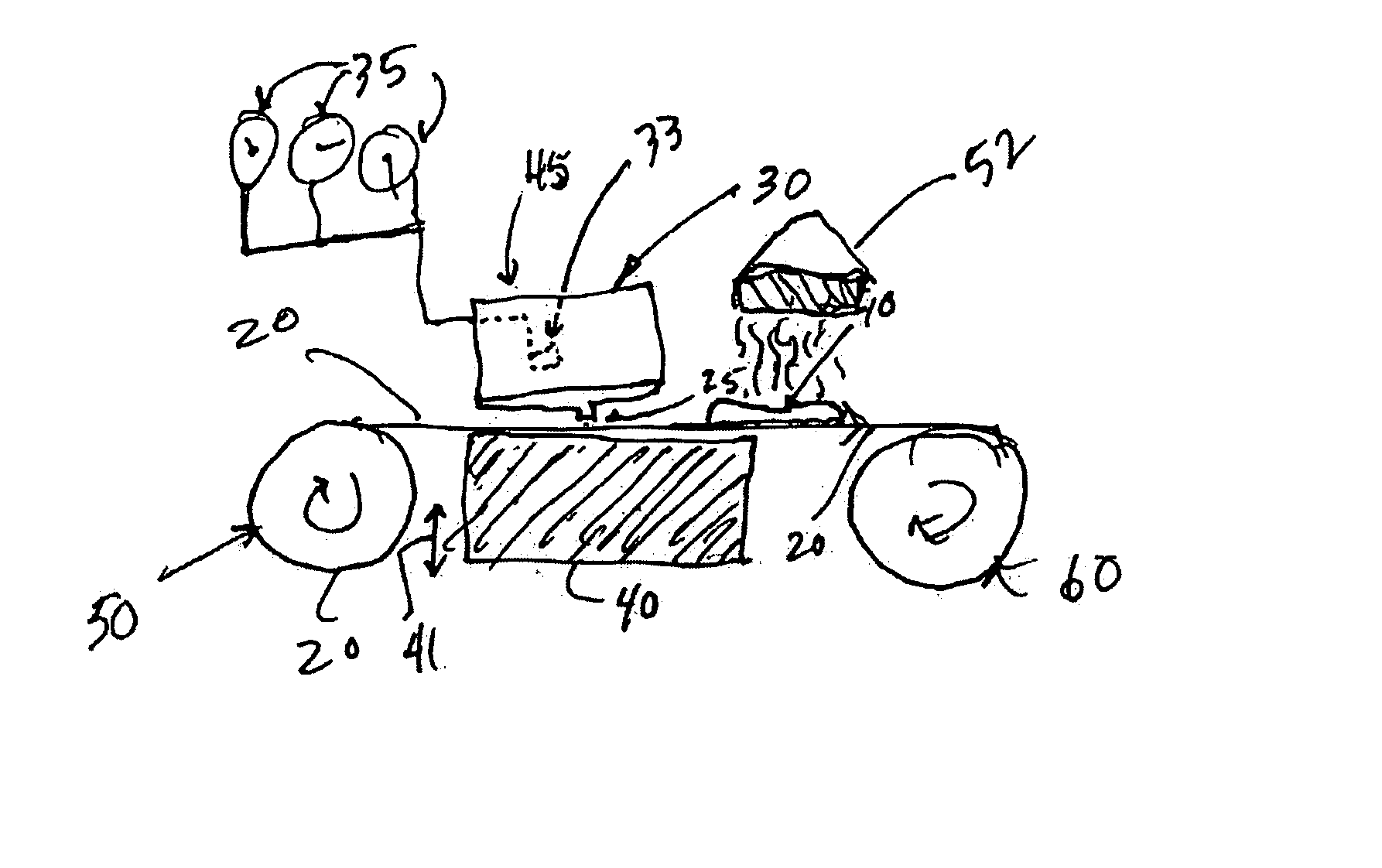
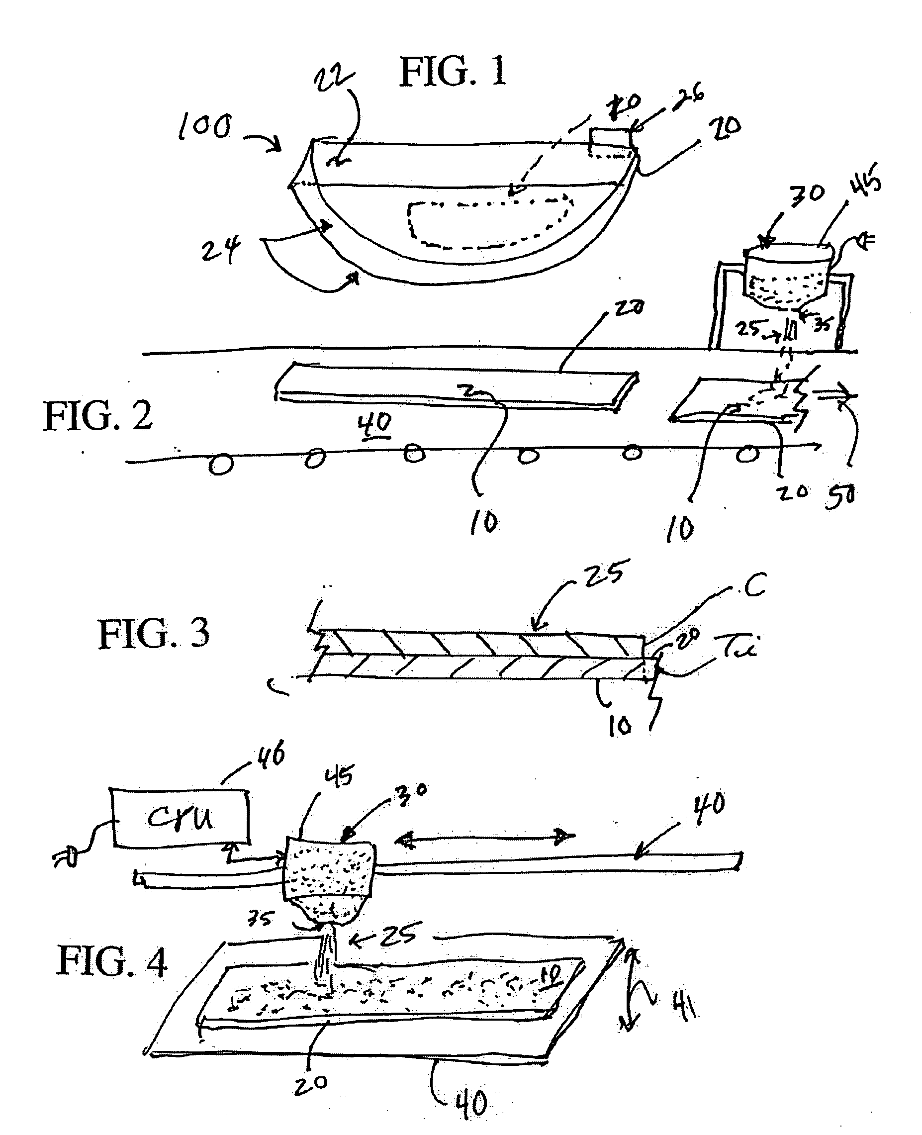
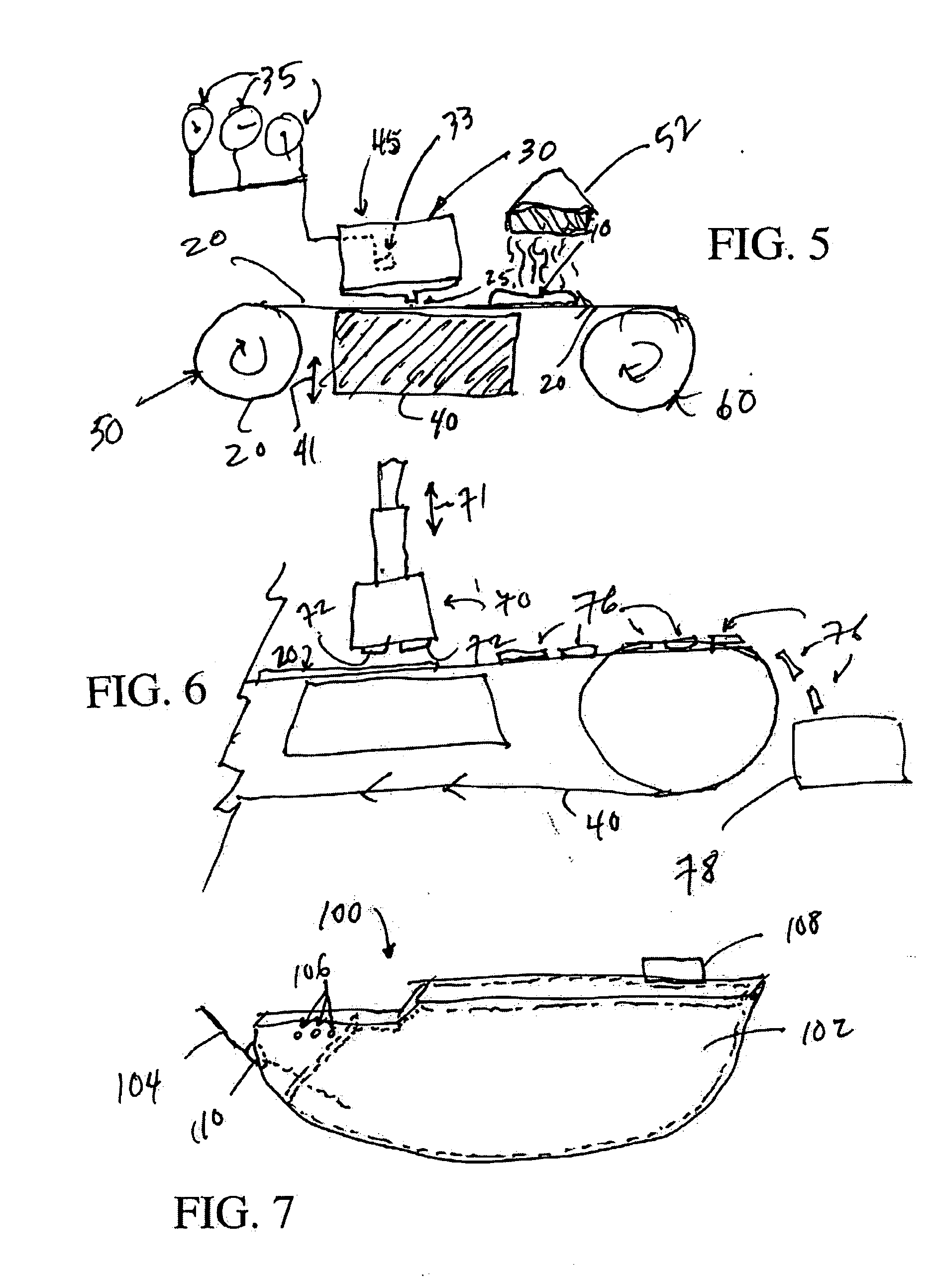
[0033] The present invention provides improved cathodes and methods for producing such cathodes for ultimate use in conjunction with valve metal capacitors. The family of cathodes according to the present invention can be produced so that they inhabit a pre-existing metallic surface such as an inner surface of a titanium casing adjacent to but insulated from direct electrical communication from an anode member. Foil-type valve metal anodes (such as aluminum) may be used in conjunction with the cathodes of the present invention; however, porous valve metal anodes (formed from metallic tantalum powder) are assumed for the purposes of the following description of the invention.

[0034] One embodiment of the present invention involves depositing a layer of carbon onto an inner surface of a titanium capacitor casing. The inner surface comprises titanium and may include a portion of the casing itself or one or more discrete titanium members disposed within said casing. Other embodiments of...


PUM

PropertyMeasurementUnit
depthaaaaaaaaaa
temperaturesaaaaaaaaaa
depthaaaaaaaaaa

Abstract

The present invention provides improved cathodes and industrialized methods for producing such cathodes using an industrial dosing valve-based electrode coating fluid emitting technique. The family of cathodes according to the present invention can be produced so that they inhabit a pre-existing metallic surface such as an inner surface of a titanium casing adjacent but insulated from direct electrical communication from an anode. Foil-type valve metal anodes as well as porous valve metal anodes formed from metallic powders may be used in conjunction with the cathodes of the present invention.

Description

CROSS REFERENCE TO RELATED APPLICATIONS [0001] The present provisional patent application relates to the subject matter of provisional U.S. patent application Ser. No. 60 / 514,371 and its corresponding non-provisional patent application Ser. No. 10 / 816,795 (Atty. Dkt. P-11709.00) filed on 23 Oct. 2003 and 2 Apr. 2004, respectively, both of which are entitled, “HIGH CAPACITANCE ELECTRODE AND METHODS OF PRODUCING SAME;” and provisional U.S. patent application Ser. No. 60 / 514,372 and its corresponding non-provisional patent application Ser. No. 10 / 817,324 (Atty. Dkt. P-11708.00) filed on 23 Oct. 2003 and 2 Apr. 2004, respectively, both of which are entitled, “METHODS OF PRODUCING CARBON LAYERS ON TITANIUM METAL;” and also relates to non-provisional U.S. patent application Ser. No. 10 / ______ (Atty. Dkt. P-21108.00) filed ______ Jun. 2004 and entitled, “METHODS AND APPARATUS FOR VAPORIZING CARBON TO FORM CATHODE LAYERS ON TITANIUM METAL VIA AN ELECTRON-BEAM” and non-provisional U.S. paten...

Claims


Application Information

Patent Timeline
Patent Type & Authority Applications(United States)
IPC IPC(8): C25B11/04H01M4/04H01M4/58
CPCH01G9/155H01M4/0404Y02E60/13H01M4/583H01M4/661H01M4/0471Y02E60/10H01G9/0425H01G9/055H01G9/048H01G9/02H01G13/00H01G13/06
Inventor HOSSICK-SCHOTT, JOACHIMSPECHT, HEIKOKRUGER, FRANKKEITEL, OLIVER
Owner MEDTRONIC INC
Why Eureka
Try Eureka