
Manufacture of bone graft substitutes

a bone graft and substitute technology, applied in the field of compositions and methods, can solve the problems of increasing pain and morbidity, unable to offer allograft granules or shapes, and the potential drawback of autogra

Inactive Publication Date: 2005-05-12
SMITH & NEPHEW INC
View PDF25 Cites 59 Cited by
  • Summary
  • Abstract
  • Description
  • Claims
  • Application Information

AI Technical Summary

Benefits of technology

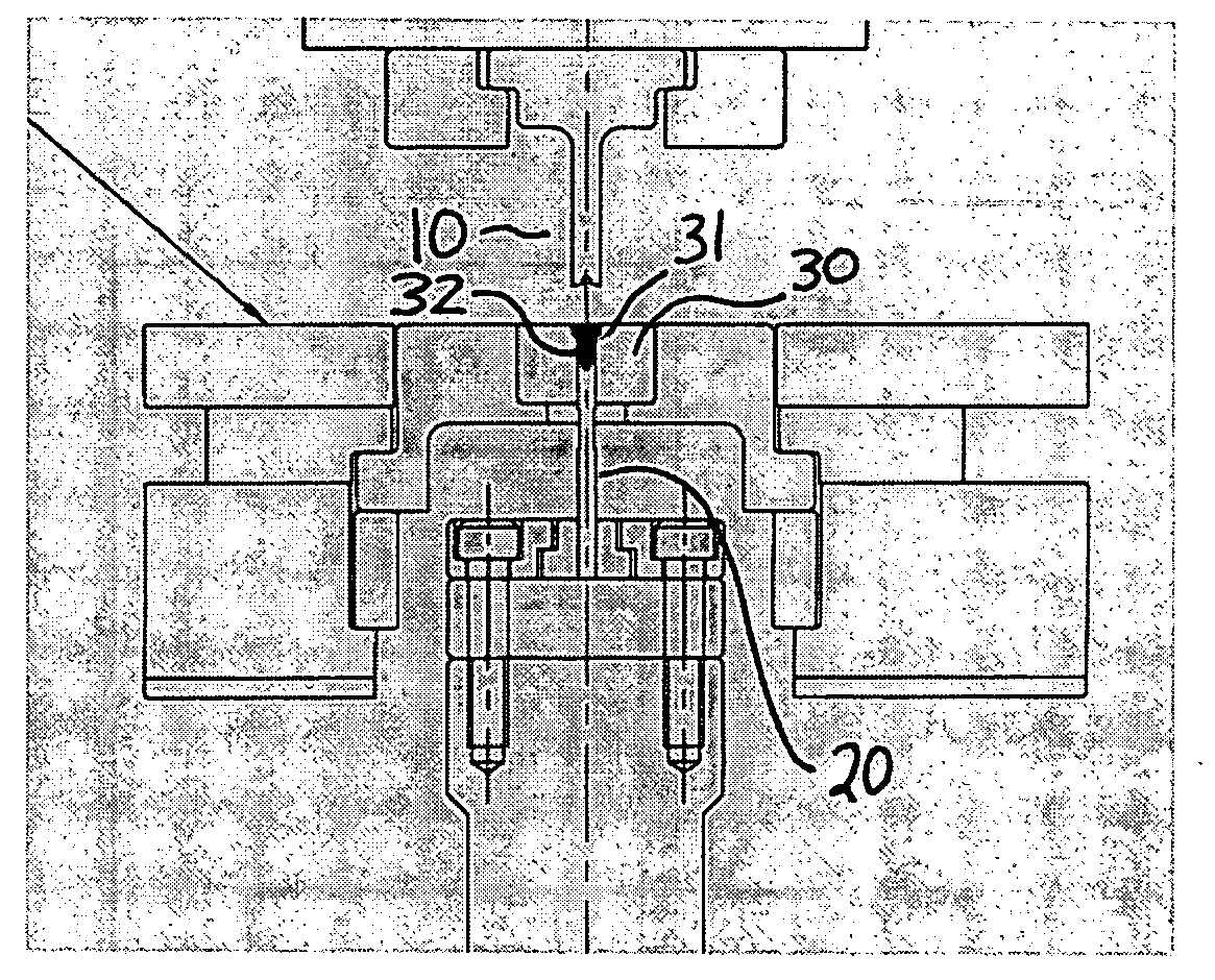
[0032] In another embodiment of the present invention, there is a method for manufacturing a shaped bone graft substitute, said method comprising the steps of: providing: a first punch having a first contact surface configured to effect a relief profile onto a surface of a bone material; a second punch having a second contact surface; and a shelf die having at least one cavity, said cavity comprising a surface configured to effect a relief profile onto a surface of the material; introducing the materi...

Problems solved by technology

However, autograft has the potential drawback of increased pain and morbidity associated with a second surgical procedure, in addition to having a limited supply of the bone.
None of the current products and technologies offered for BGS is capable of offering an allograft granule or shape for easy delivery and scaffold structure, in addition to being conformable to the surgical site.
Furthermore, none but one (Osteoset®-T) of the current products and technologies offered for BGS is capable of offering an allograft or synthetic granule or shape containing a bioactive agent or agents, such as an antibiotic or bone morphogenetic proteins.
However, it is a disadvantage of most presently available products to have no shape that provides significant stability, such as by interlocking.
Furthermore, the irregularly-shaped chips of presently available products do not compact sufficiently and also fail to generate reproducible results.
Although U.S. Pat. No. 6,630,153 is directed to a method of manufacturing a three-dimensional intricately shaped bone graft substitute comprising the step of dry powder compacting a bone material into the three-dimensional intricate shape, for some particular embodiments, such as smaller sized substitutes, the method is not optimally suited.

Method used


Image

  • Manufacture of bone graft substitutes
  • Manufacture of bone graft substitutes
  • Manufacture of bone graft substitutes

Examples


example 1

Generation of Bone Graft Substitutes

[0129] Bone graft substitutes are generated by methods as described herein. Generally, a bone material, such as a powder, for example, is provided for the bone graft substitute. In some embodiments, additional material may be added before the pressing steps. For example, a processing aid may be added to the bone material. Upon blending of a processing aid with the bone material, the shaped bone graft substitutes are generated with the novel dry powder compaction processes of the present invention.

[0130] In particular embodiments, tricalcium phosphate (TCP) is the bone material utilized. In a particular embodiment, the following TCP powder materials are utilized: P240R L2; and P240RL2-600. In further specific embodiments, both powders were blended with 2.5 wt. % calcium stearate (processing aid and binder) to make 200-250 g batches. Exemplary-shaped TCP JAX granules (such as, for example, granules being about 4 mm tip to tip) were formed using dr...

example 2

Processing Aid Selection for TCP Bone Graft Substitutes

[0134] This example characerizes the use of two processing aids, calcium stearate (CaSt) and magnesium stearate (MgSt), for powder compaction of TCP BGS, and in a non-limiting exemplary embodiment are JAX granules. The amount of processing aid (2.5 wt. %) had been selected based on preliminary powder compaction studies. As described herein, TCP JAX granules were powder compacted and sintered at various temperatures and tested for density and friability.

Materials and Methods

[0135] Processing of TCP Granules

[0136] The TCP powder (Lot # P240R, 75-125 μm, Plasma Biotal, Ltd., Tideswell, UK) was mixed with either 2.5 wt % calcium stearate (Lot# ASC0229, NF Grade, KIC Chemicals, Armonk, N.Y.) or 2.5 wt % magnesium stearate (Lot# ASC0101, NF Grade, KIC Chemicals, Armonk, N.Y.) in a V shell blender. The powder blends were compacted under a load of 2.5 kN at a rate of 30 strokes (parts) per minute to produce the 6-arm TCP JAX shape ...

example 3

Biological Agents

[0152] In a preferred embodiment of the present invention, a biological agent is included in the bone material, such as a powder, or on the generated shape, or both. Examples include antibiotics, growth factors, proteins, fibrin, bone morphogenetic factors, bone growth agents, chemotherapeutics, pain killers, bisphosphonates, strontium salt, fluoride salt, magnesium salt, sodium salt, or mixtures thereof.

[0153] In contrast to administering high doses of antibiotic orally to an organism, the present invention allows antibiotics to be included within and / or on the composition for a local administration. This reduces the amount of antibiotic required for treatment of or prophalaxis for an infection. Administration of the antibiotic in the BGS would also allow less diffusing of the antibiotic, particularly if the antibiotic is contained within a partially confining material, such as a fibrin matrix. Alternatively, the particles of the present invention may be coated w...


PUM

PropertyMeasurementUnit
Massaaaaaaaaaa
Massaaaaaaaaaa
Massaaaaaaaaaa

Abstract

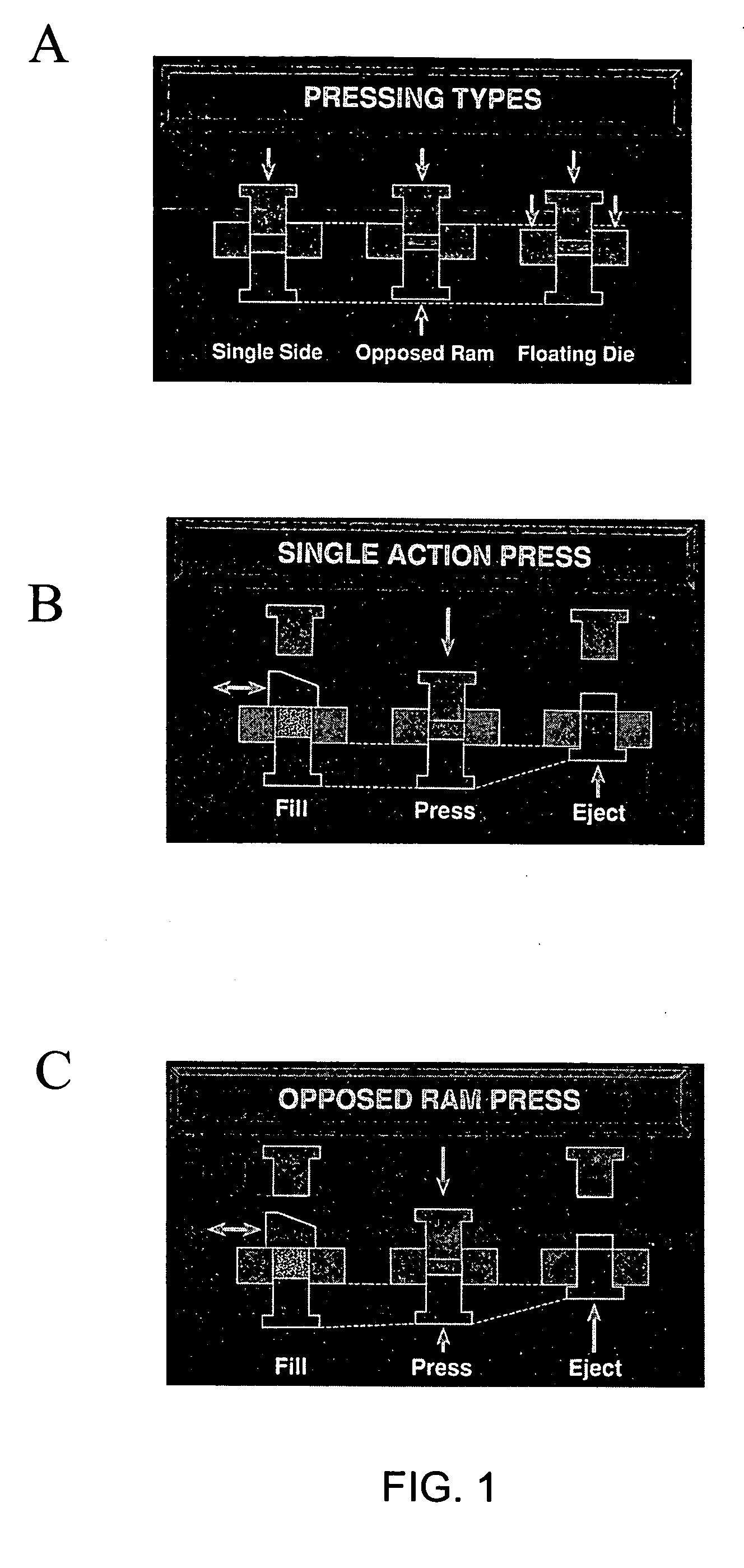
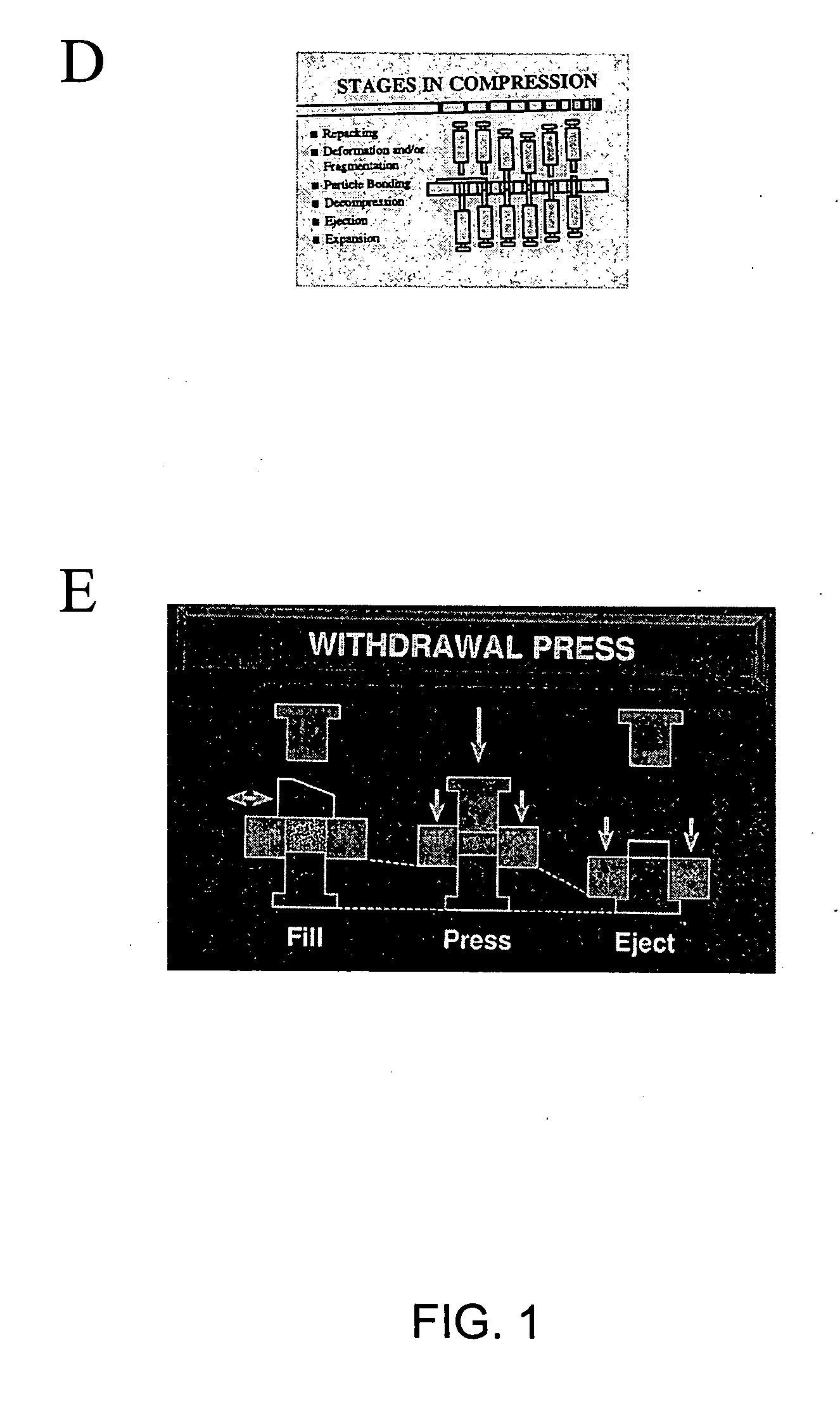
The present invention is directed to methods and compositions for manufacturing a bone graft substitute. A powder compaction process is utilized to generate a shaped product comprised of a bone material and in some embodiments a processing aid is utilized to facilitate compaction of the bone material and / or for release of the product from the die. In one aspect of the present invention, the manufacturing process comprises a withdrawal press having a shelf die, a lower punch, and an upper punch, wherein at least both the shelf die and lower punch are configured to impart at least part of the shape of the particle upon the material.

Description

FIELD OF THE INVENTION [0001] The present invention is directed to compositions and methods for making bone graft substitutes. More specifically, the present invention is directed to manufacturing a bone graft substitute (BGS) by powder compaction utilizing a shelf die and at least one punch, both of which impart a relief profile upon bone material to manufacture the shape of the BGS. BACKGROUND OF THE INVENTION [0002] Bone graft is used to fill spaces in bone tissue that are the result of trauma, disease degeneration or other loss and / or defect of tissue. Clinicians perform bone graft procedures for a variety of reasons, often to fill a bone void created by a loss of bone, compaction of cancellous bone, and / or correction or improvement of bone. In many instances, the clinician also must rely on the bone graft material to provide some mechanical support, as in the case of subchondral bone replacement or compaction grafting around total joint replacement devices. In these instances, ...

Claims


Application Information

Patent Timeline
IPC IPC(8): A61F2/00A61F2/28A61F2/30A61F2/46B29C43/00
CPCA61F2/28B29L2031/7532A61F2002/2817A61F2002/2835A61F2002/30677A61F2002/30957A61F2002/30968A61F2310/00179A61F2310/00203A61F2310/00215A61F2310/00239A61F2310/00293A61F2310/00329B29C43/003B29K2105/251A61F2/4644
Inventor LONG, MARCHOLBROOK, JEFFMARGERRISON, ED
Owner SMITH & NEPHEW INC
Learn More