

Voltage to current converter and method for converting
- Summary
- Abstract
- Description
- Claims
- Application Information
AI Technical Summary
Benefits of technology
Problems solved by technology
Method used
Image


Examples
Embodiment Construction
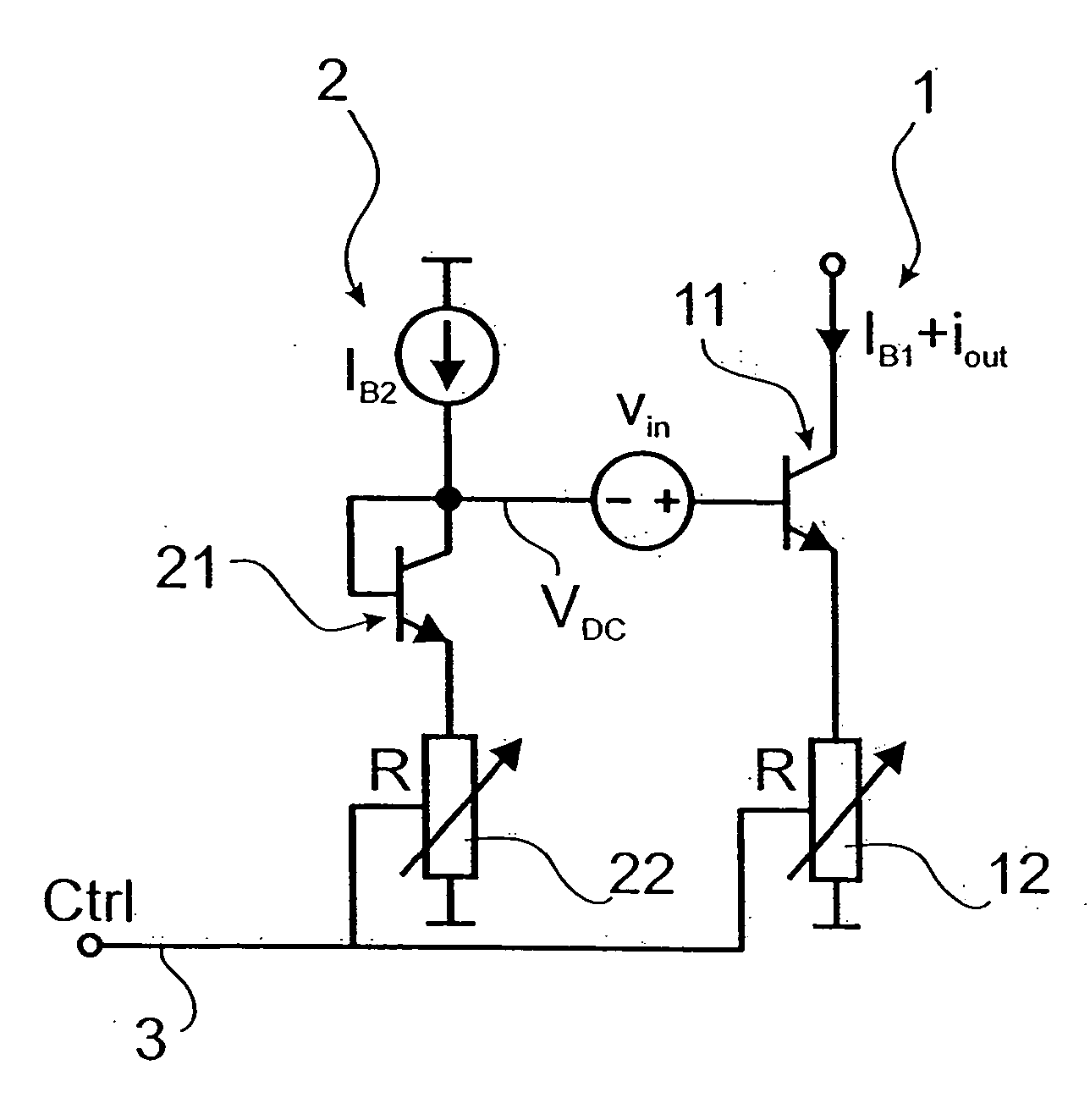
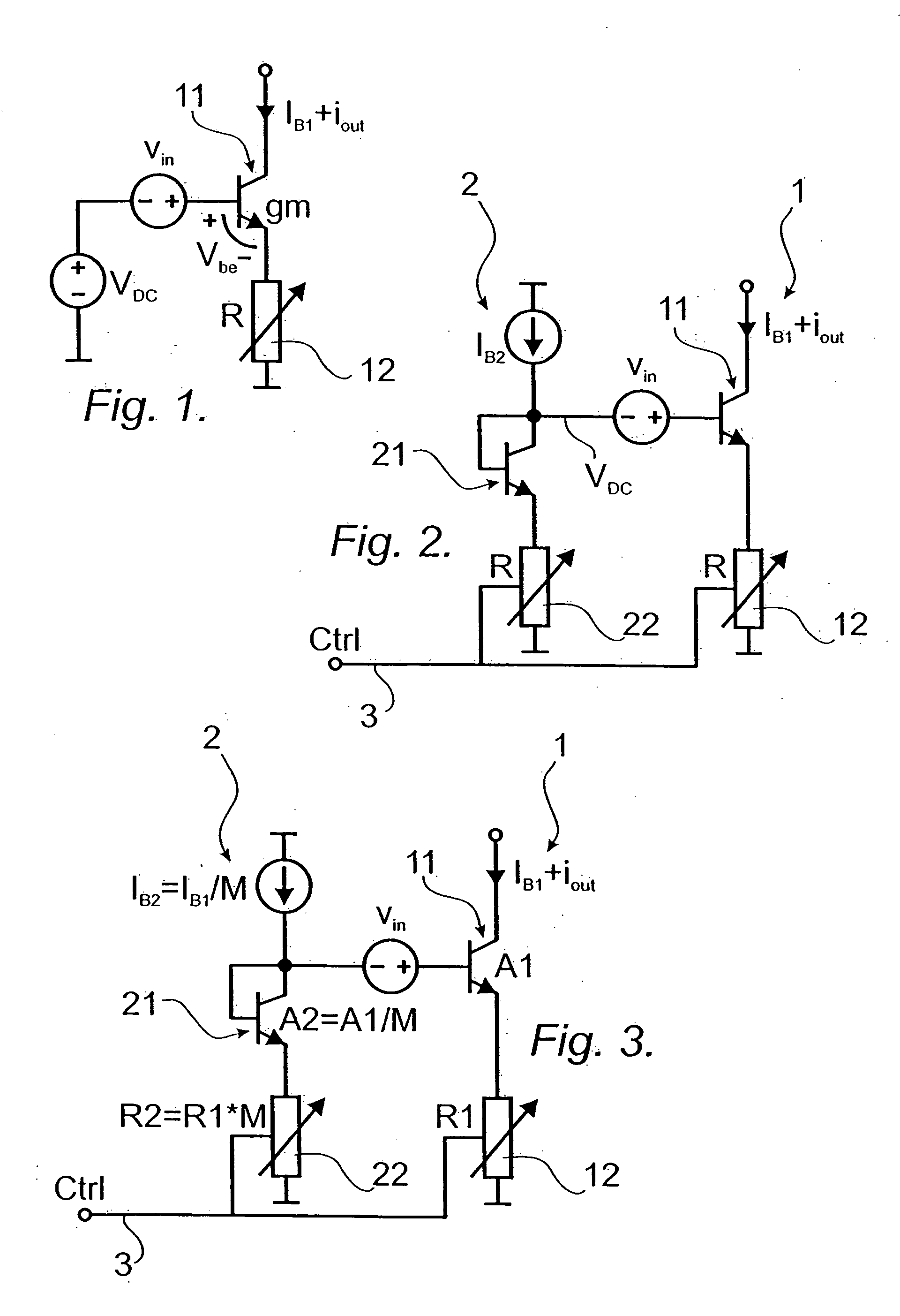
[0022] With reference to FIG. 1, a voltage to current converter according to prior art is described. The known converter comprises a first transistor 11 and a first resistor 12, where the first transistor 11 is adapted to be fed with an input DC bias voltage VDC and an input signal voltage vin, and where the converter is adapted to generate an output current, comprising an output DC bias current IB1 and an output signal current iout.
[0023] The converter is adapted to provide a gain adjustment through the variation of the first resistor 12.
[0024] The voltage to current transfer function can be expressed as: ioutvi n=gm1+gm·R
[0025] Where gm is the transconductance of the first transistor 11 and R is the resistance of the first resistor 12. Providing the transconductance gm of the first transistor 11 is large (gm>>1 / R) the voltage to current transfer function can be expressed as: ioutvi n=1R
[0026] A straightforward way to implement adjustable gain is to make the resistance R ad...
PUM
 Abstract
Description
Claims
Application Information