

Device and system for phase conjugate conversion and wavelength conversion
- Summary
- Abstract
- Description
- Claims
- Application Information
AI Technical Summary
Benefits of technology
Problems solved by technology
Method used
Image

Examples
Embodiment Construction
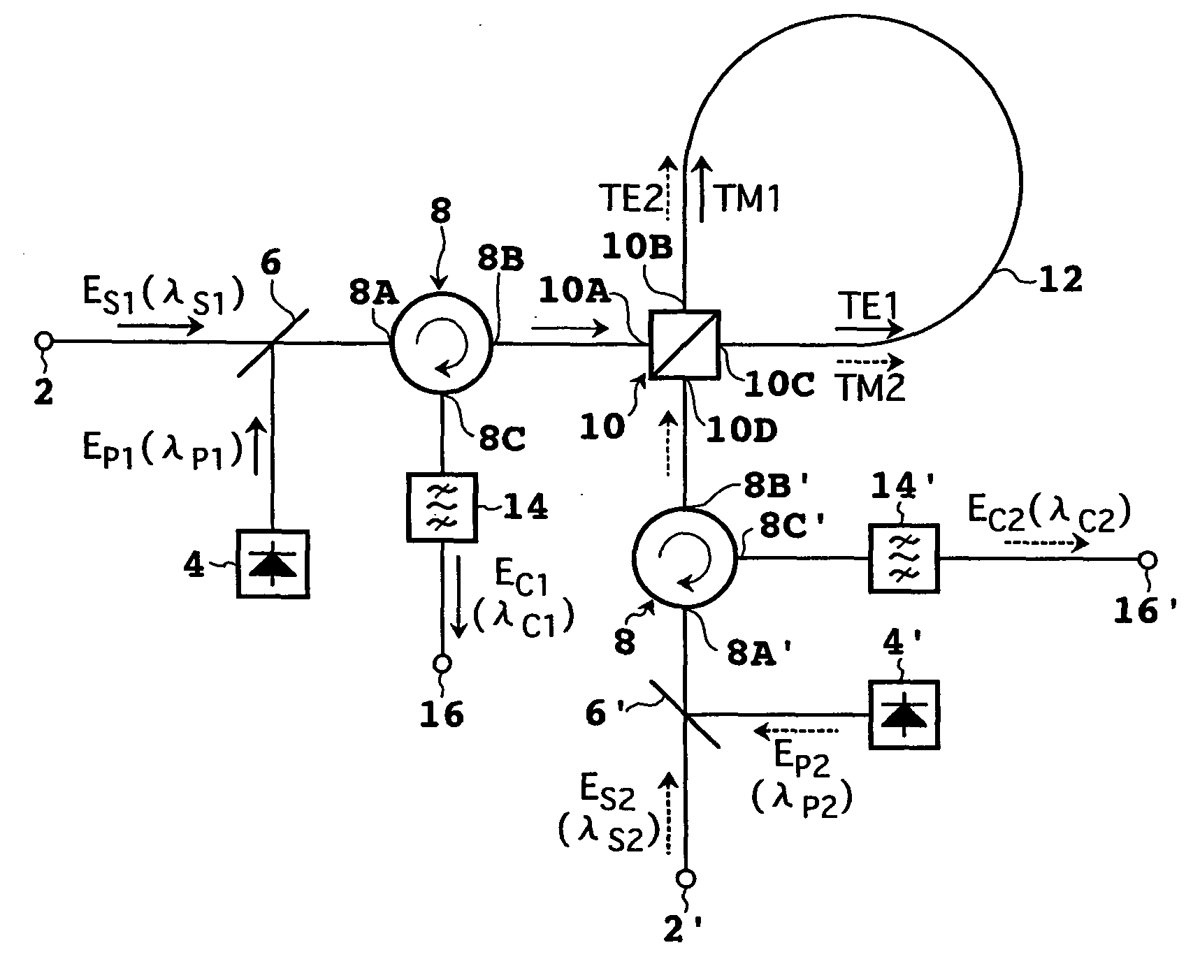
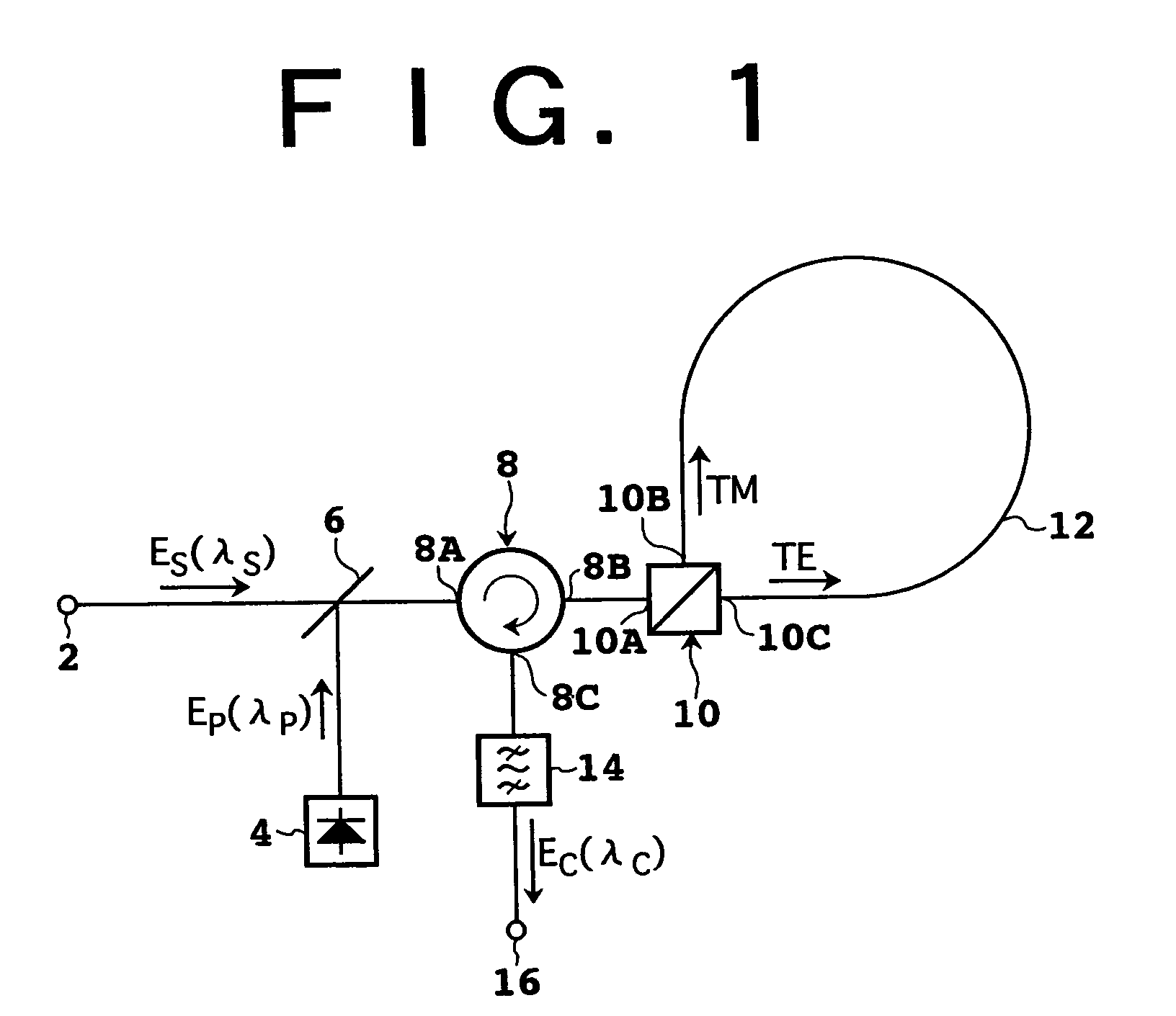
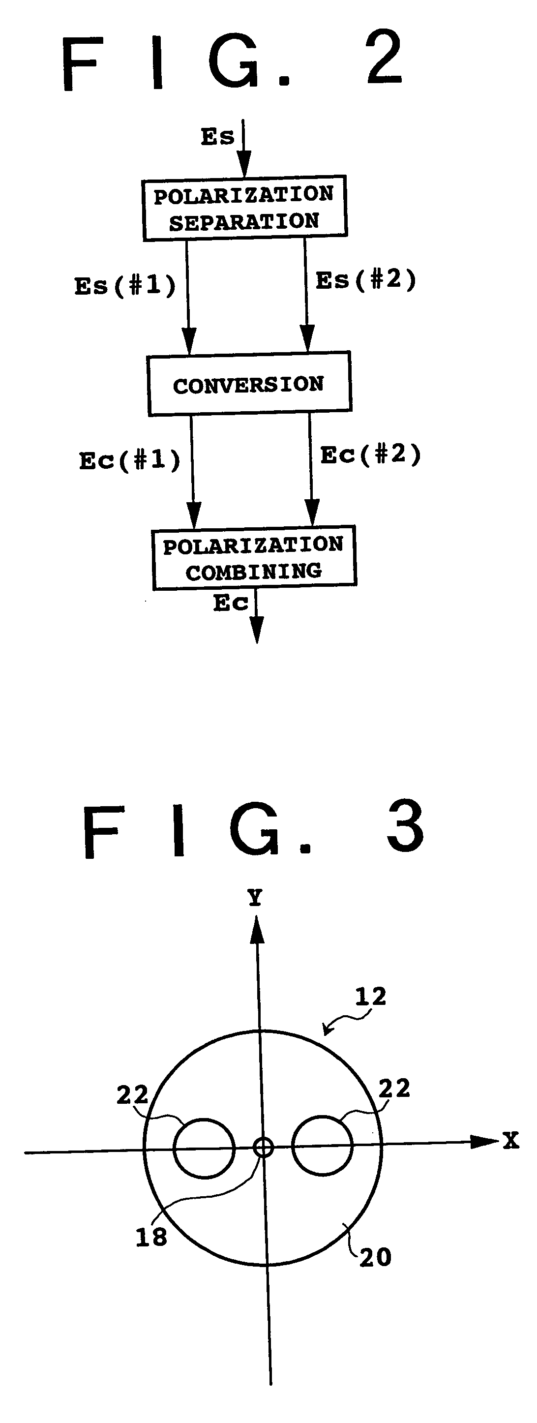
[0054] Some preferred embodiments of the present invention will now be described in detail with reference to the attached drawings.
[0055] Let us consider the case where an optical pulse propagates in a dispersive medium. In the case that the dispersive medium is a normal dispersive medium (∂2β / ∂ω2>0), the frequency of an unchirped pulse propagating in the dispersive medium is shifted to lower frequencies near the leading edge of the pulse, and is shifted to higher frequencies near the trailing edge of the pulse. In the case that the dispersive medium is an anomalous dispersive medium (∂2β / ∂ω2<0), the frequency of an unchirped pulse is shifted to higher frequencies near the leading edge of the pulse, and is shifted to lower frequencies near the trailing edge of the pulse. In the above expressions, β and ω denote the propagation constant and the angular frequency of light, respectively. In the normal dispersive medium, the longer the wavelength of the pulse, the higher the group velo...
PUM
 Abstract
Description
Claims
Application Information