Fuel level sensor

a technology of electric position and sensor, applied in the direction of liquid/fluent solid measurement, machines/engines, instruments, etc., can solve the problems of high component cost, wear of contact type sensors, ultrasonic, electromagnetic, shaped electromagnetic field sensors, etc., and achieve easy installation, accurate measurement of rotational position or linear position, and easy adaptability

Inactive Publication Date: 2005-05-19
UUSI
View PDF12 Cites 60 Cited by
  • Summary
  • Abstract
  • Description
  • Claims
  • Application Information

AI Technical Summary

Benefits of technology

[0022] The present invention concerns an easy to install, reliable, and accurate fluid level sensor. One embodiment of the invention concerns a fuel level sensor. However, the design can be easily adapted to other fluid level sensing applications like engine oil, radiator fluid, brake fluid, and power steering fluid. Still other applications can include

Problems solved by technology

It is known that such contact type sensors wear over time, making non-contact type sensors desirable.
Ultrasonic, electromagnetic, and shaped electromagnetic field sensors have complex electronics to drive the sensor element and determine the fuel level.
Their complexity makes component costs high.
Although regarded as low cost, the resistor card is not a cost effective solution for fuel level sensing when its characteristics of product reliability and service life are considered.
The major fault of the resistor card is its reliance on a mechanical wiper to maintain electrical contact to the resistive element within its assembly.
Level sensors that incorporate a mechanical contact have a number of well-known problems.
The mechanical movements within any mechanism make those components susceptible to wear, fatigue, and loosening.
This is a progressive problem that occurs with use and leads to eventual failure after a sufficient amount of movement has occurred.
In fuel level sensing, a source of mechanical failure for the resistor card comes from fluid sloshing inside the fuel tank thus creating unwanted twisting and levering of the float and float arm.
Under these conditions the wiper may eventually fatigue losing its spring characteristics and may even loosen from its rotational pivot hub.
Eventually the wiper will lose

Method used


Image

  • Fuel level sensor
  • Fuel level sensor
  • Fuel level sensor

Examples


Embodiment Construction

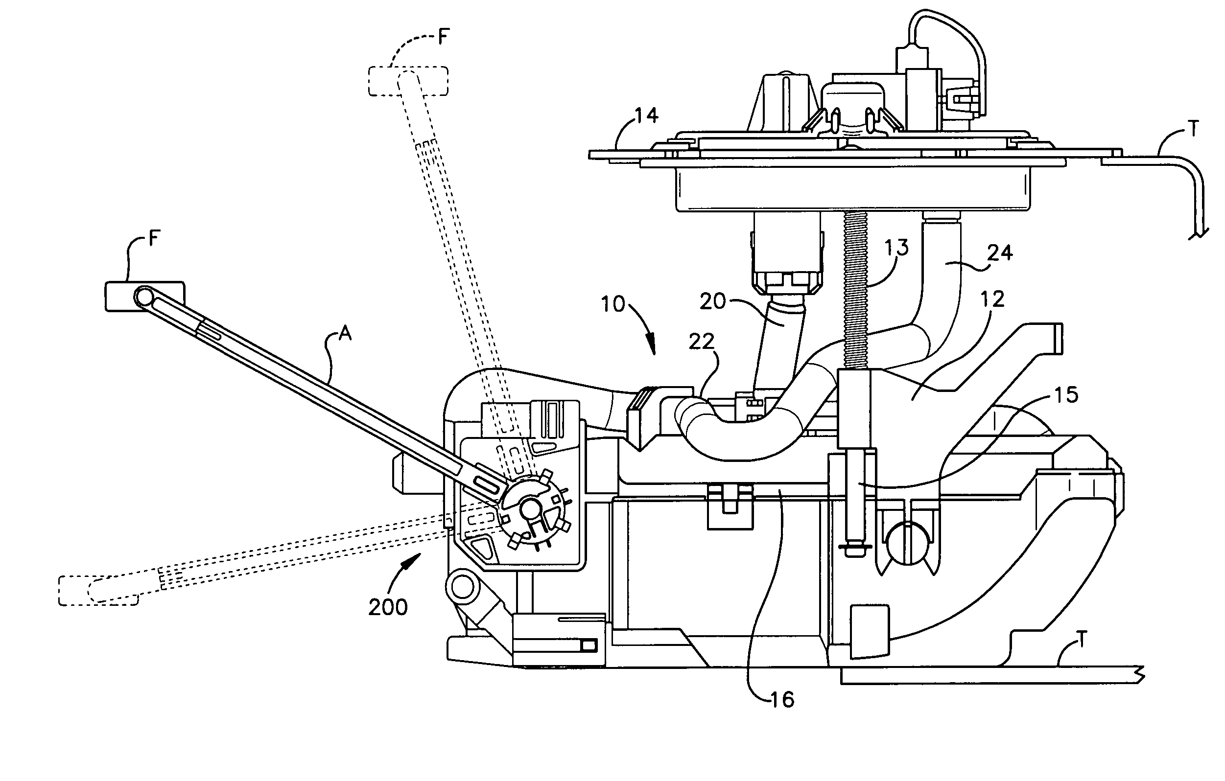
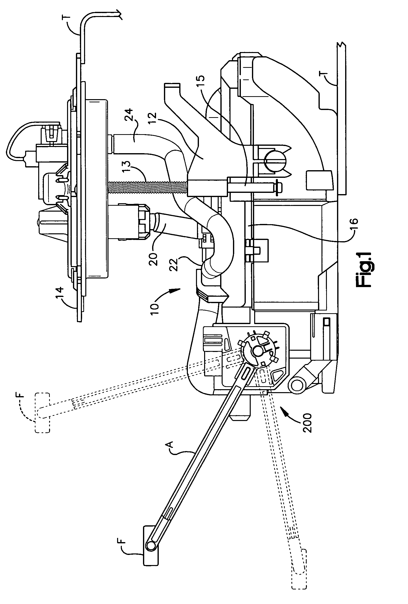
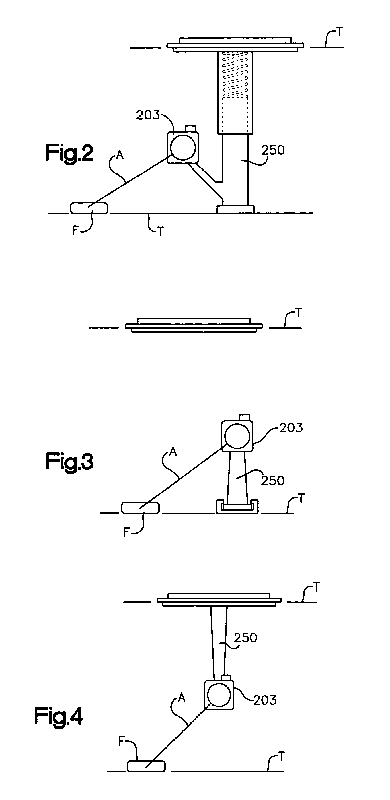
[0045] Several exemplary embodiments of the invention are disclosed. These alternate embodiments translate a position of a float into the rotational movement of a magnet support and associated magnet. A presently preferred embodiment uses a traditional rigid float arm that attaches the float to a magnet hub. The longer a float arm is, the less angular rotation of the magnet hub will occur for the same linear travel of the float. Likewise, a shorter float arm will yield more angular rotation for the same linear travel of the float. In fluid level sensing, the float arm travel is limited to less than 180 degrees of motion. This is well suited for a Hall effect sensor.

[0046] If the relationship formed between the float's travel, float arm length, and magnet hub angular rotation is not favorable to the application, a gear assembly could be implemented to either reduce or increase the angular rotation of the magnet hub for given travel of the float.

[0047] Other methods of coupling the ...


PUM


Abstract

A fuel level sensor for sensing and monitoring the level of remaining fluid in a container such as a fuel tank for a motorized vehicle is disclosed. The fuel level sensor incorporates an improved float and pivot arm member attached to a hub that rotates about a pivot base. The conventional resistor card technology, commonly found in automotive applications for translating the position of the float into an electrical signal, is replaced by a more reliable non-contact magnetic flux sensing circuit. The fuel level sensor incorporates a magnetic sensor and magnetic circuit in a commonly known and practiced rotational position sensor configuration for determining the angular position of a hub relative to its pivot base, where the hub is attached to a conventional float-arm member and the base remains stationary relative to the fuel container. The preferred embodiment includes a magnetic flux sensor positioned between two movable magnets. The magnetic flux sensing element is a Hall effect integrated circuit, magnetoresistor, magnetodiode, magnetotransistor, or similar magnetic flux sensing element with associated electronic circuitry having adjustable or programmable features including ratiometry, gain, offset voltage, temperature coefficient, and output signal range limiting. Critical electronic components are hermetically sealed making the fuel level sensor fully submersible in fuel for long term fuel exposure.

Description

CROSS REFERENCE TO RELATED APPLICATIONS [0001] The present application relates to U.S. patent application Ser. No. 09 / 325,883, filed Jun. 4, 1999 now U.S. Pat. No. 6,396,259, entitled Electronic Throttle Control Position Sensor. The subject matter of this application is incorporated herein by reference.BACKGROUND OF THE INVENTION [0002] 1. Field of the Invention [0003] This invention relates to an electrical position sensing circuit and particularly a liquid level sensing circuit used to make possible a non-contact electronic fuel level sensor for measuring the amount of fuel remaining in a motor vehicle gas tank. [0004] 2. Background Art [0005] Fuel level sensors known for monitoring the level of fuel within a gas tank are resistive, ultrasonic, electromagnetic, and shaped electromagnetic field in nature. Resistive type sensors rely on contact connections to a resistive element. A float and a pivot arm move such that when the fuel tank is full, the wiper contact is at one extreme o...

Claims


Application Information

Patent Timeline
IPC IPC(8): G01FG01F23/32G01F23/38G01F23/52G01F23/54
CPCG01F23/32G01F23/54G01F23/38
Inventor NEWMAN, TODD R.WASHELESKI, JOHN
Owner UUSI
Why Eureka
Try Eureka