Electric energy storage system

a technology of electric energy storage and energy storage system, which is applied in the direction of cell components, final product manufacturing, sustainable manufacturing/processing, etc., can solve the problems of short cycle life of electric energy storage system, inability to quickly charge and discharge, and increase in requirements, so as to achieve fast charging and discharge, short cycle life, and low energy density

Inactive Publication Date: 2005-05-19
NESS CAPACITOR CO LTD
View PDF2 Cites 8 Cited by
  • Summary
  • Abstract
  • Description
  • Claims
  • Application Information

AI Technical Summary

Benefits of technology

[0014] In order to overcome the above problems in the conventional lithium rechargeable battery such as short cycle life and slow charging-discharging characteristics, and a low energy density that is one defect of an electrochemical capacitor, it is an object of the present invention to provide an electric energy storage system having a novel structure which exhibits a long cycle life, rapid charging-discharging characteristics and a high energy density.

Problems solved by technology

However, the lithium rechargeable battery can not be applied to an electric automobile, wherein the requirement rises suddenly, considering too short charging and discharging life time.
However, due to a driving principle, the electric energy storage system has a short cycle life and can not be promptly charged and discharged.
An electric energy storage system of the lithium rechargeable battery can not satisfy such technical requirement.
Moreover, it is known that a repeated rapid discharging-charging rapidly shortens the cycle life thereof.
Therefore, since the process producing the electric double layer is a rapid electrochemical reaction and does not give a structural impact on the active materials, the electric double layers show a long cycle life and rapid charging-discharging characters.
However, the surface area of the activated carbon used for the active material can not be expanded infinitely and the capacity for storing an electric energy obtained from the electric double layer is very low as compared with an electrochemical oxidation-reduction reaction, so that it might be impossible to obtain a high energy density.
However, the EDLC has a fatal weak point that the energy density is very low, as compared with a rechargeable battery.
Also, a manufacturing cost of ruthenium dioxide is very high, so that ruthenium dioxide can not be actually employed for an active material of an electrode.
According to the above-mentioned disclosure, when only one kind of salt is used, satisfactory results can not be obtained.
When lithium ion is used only, an electric conductivity becomes low, so that the pseudocapacitor can not function as a capacitor.

Method used


Image

  • Electric energy storage system
  • Electric energy storage system
  • Electric energy storage system

Examples


example 1

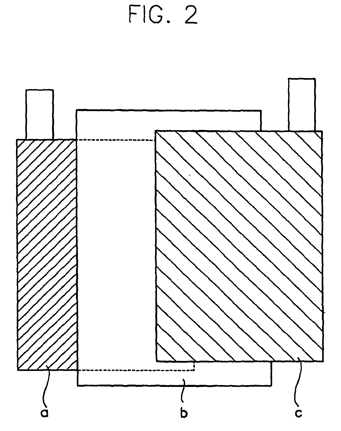
[0059] As an anode active material, LiCoO2 including lithium was used and as an cathode active material, BP (trade name manufactured by Kuraray Co. Ltd., Japan), a kind of activated carbon was used. After the active materials of each electrodes ware mixed with conductive carbon in a ratio of 8 to 2 by weight, water that includes a binder PVdF of 10 wt. % in a dissolved state was added thereto and then they were mixed, so as to prepare slurry. An aluminum foil having a thickness of 20 mm was coated with the resultant slurry, and then the coated aluminum foil was dried in a dryer at a temperature of 120° C., to complete an electrode.

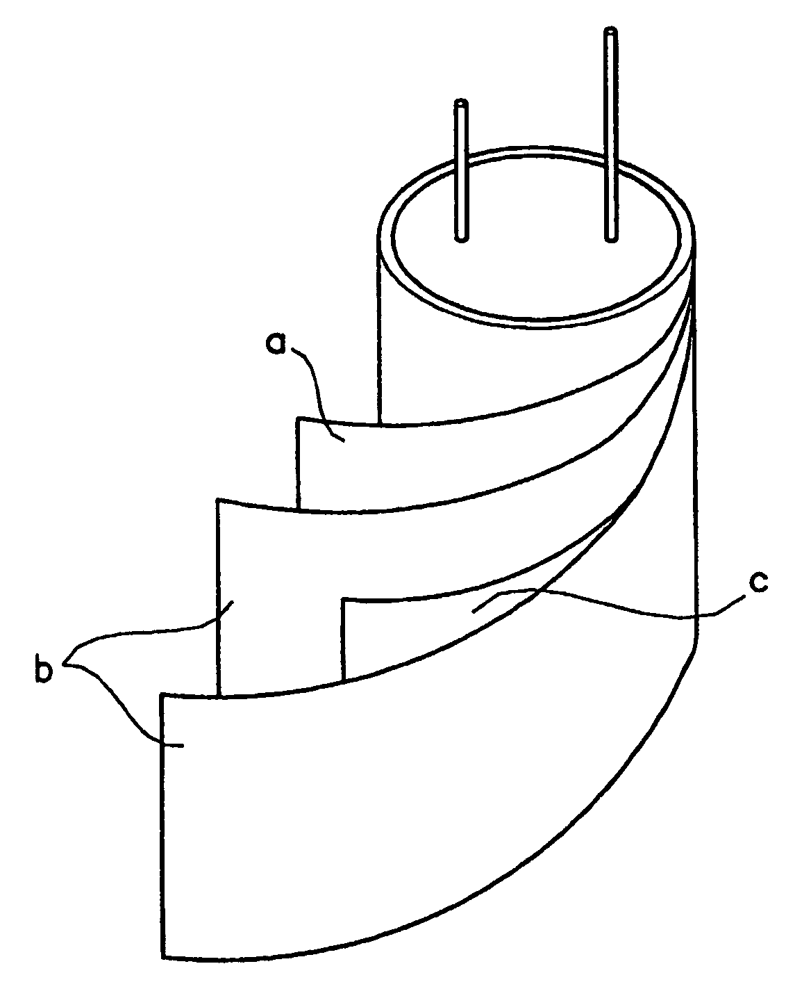
[0060] Thus prepared electrodes were assembled together, by interposing a separating insulation membrane therebetween as shown in FIG. 1. The electrolyte was comprised of acetonitrile as a solvent and LiPF6 of 1.0 M and tetraethylammonium tetrafluoroborate of 1.0 M as a solute. At this time, the surface area of each of the electrodes was 150 cm2 and the a...

experimental example 1

[0061] When voltage of 2.5V was applied to both anode and cathode of the electric energy storage system prepared in Example 1, the respective measured values of the voltage applied to anode and cathode are shown in FIG. 3.

[0062] During the electric potential is applied from 1V to 2.5V, the electric potential applied to the anode was actually changed from 4.1V to 4.8 V vs. Li / Li+ and the electric potential to cathode was changed from 3.08V to 1.69 V vs. Li / Li+.

[0063] As a result, changes in the electric potentials in the present system were almost observed on the cathode. Accordingly, it can be noted that an electrochemical impact when storing an electric energy has occurred on the cathode not the anode. This is the reason why a structurally fragile anode can be protected and the present electric energy storage system has a long life time and rapid charging and discharging characters.

experimental example 2

[0064] The measured CV value of the electric energy storage system prepared in Example 1 by a voltage scan method is shown in FIG. 4. As illustrated in FIG. 4, the measured value of CV is similar to that of an electrochemical capacitor.


PUM

PropertyMeasurementUnit
specific surface areaaaaaaaaaaa
temperatureaaaaaaaaaa
thicknessaaaaaaaaaa

Abstract

An electric energy storage system having a novel structure which exhibits a ling cycle life, rapid charging-discharging characteristics and a high energy density. The electric energy storage system comprises: an anode comprised of a first material that performs interalation-deintercalation of cation as an anode active material; a cathode comprised of a second material that may form an electric doublelayer with anion as a cathode active materials; and a electrolyte including lithium salt, the electrolyte including the cation and anion. Due to a high difference between anode and cathode in capacity to store the electric energy, most electrochemical impact that occurs in the process of intercalation-deintercalation of electric energy is absorbed into cathode and active material used for anode is activated carbon having a very high resistance to electrochemical and structural impact, so that its operation life is elongated and it has rapid charging-discharging characteristics. The electric energy storage system can complement the defects of a conventional technology.

Description

TECHNICAL FIELD [0001] The present invention relates to an electric energy storage system, and more particularly, to a novel electric energy storage system prepared by employing a transitional metallic oxide including lithium as an active material of an anode and an activated carbon as an active material of a cathode. BACKGROUND ART [0002] Conventionally, as the representative conventional devices for storing electric energy, battery, capacitor, etc. may be mentioned. Specifically, a lithium rechargeable battery and an electrochemical capacitor are typical examples of the electric energy storage system. Since the lithium rechargeable battery has a high energy capacity, it is recently applied widely. [0003] The lithium rechargeable battery is recently being used as an energy storage system attached to many portable electric equipments and has a high energy density, so that it began to occupy market share in market of the conventional rechargeable battery such as Ni—Cd rechargeable ba...

Claims


Application Information

Patent Timeline
Patent Type & Authority Applications(United States)
IPC IPC(8): H01G9/00H01M4/131H01M4/48H01M4/485H01M4/50H01M4/505H01M4/52H01M4/525H01M10/04H01M10/0568
CPCH01G9/155H01M4/131H01M4/485Y02E60/13H01M4/525H01M10/0568H01M12/005H01M4/505Y02E60/10Y02P70/50H01G11/02H01G11/50H01G11/06H01G11/32H01G11/46H01G11/24
Inventor LEE, HEE-YOUNGLEE, HA-YOUNGKIM, HEUI-SOO
Owner NESS CAPACITOR CO LTD
Why Eureka
Try Eureka