Multi-fibre arrangement for high power fibre lasers and amplifiers

a multi-fibre arrangement, high-power technology, applied in the direction of fiber transmission, lasers, transmission, etc., can solve the problems of high cost, insufficient power output of amplifiers, and prone to pump source failure of conventional amplifiers, so as to improve pump absorption and thereby efficiency, the effect of small outer diameter and reducing the ratio of passive-cladding to active-core volum

Inactive Publication Date: 2005-05-19
SPI LASERS UK
View PDF8 Cites 66 Cited by
  • Summary
  • Abstract
  • Description
  • Claims
  • Application Information

AI Technical Summary

Benefits of technology

[0041] 6. It eliminates the requirement (in a prior-art cladding-pumped fibre amplifier or fibre laser) that the fibre from which this new structure is made must be able to guide the pump i.e., is large enough and with sufficient NA (and assuming that the amplifier or laser structure is made by coiling a fibre). Thus, a fibre with a much smaller outer diameter and hence a much lower passive-cladding to active-core volume ratio (=area ratio) can be used. This improves pump absorption and thereby efficiency. Instead, it is enough that the structure as a whole can guide the pump. For instance, a pump coupler can be side-spliced to the structure rather than to a single point on a single fibre or the pump energy can be introduced with a plurality of pump optical fibres that can be of such a size that they can be located in the interstitial spaces within the coil.
[0042] 7. It eliminates the need for special geometries for improved pump...

Problems solved by technology

Such amplifiers provide limited power output that is insufficient for multi-channel WDM transmission systems.
In addition, conventional amplifiers are prone to the failure of pump sources, requiring several pump sources to be contained with the amplifier in order to provide pump redundancy—but at high cost.
Although the output power obtainable from such an optical amplifier containing one of these pump modules is sufficient for amplifying many channels simultaneously, the approach is expensive, is currently limited in powers to around 1 W, and offers limited pump redundancy.
However, it is cumbersome to separate the signal path to the single-mode core from the path required to launch pump powers into the inner cladding.
However, none of these techniques provides a simple, effective way of reliably introducing the pump energy into the optical amplifier or fibre laser—especially if several pump lasers are required in order to provide pump redundancy.
This issue is of concern for high-power fibre lasers where there is a requirement to introduce the pump-energy from several to tens of pump diodes into the laser cavity.
No effective, reliable and cost-effective way to achieve this exists in the prior art.
An associated problem is that introducing signal conditioning into the optical amplifier can be difficult.
This requires ready access to the signal, which can be difficult for most a...

Method used


Image

  • Multi-fibre arrangement for high power fibre lasers and amplifiers
  • Multi-fibre arrangement for high power fibre lasers and amplifiers
  • Multi-fibre arrangement for high power fibre lasers and amplifiers

Examples


example i

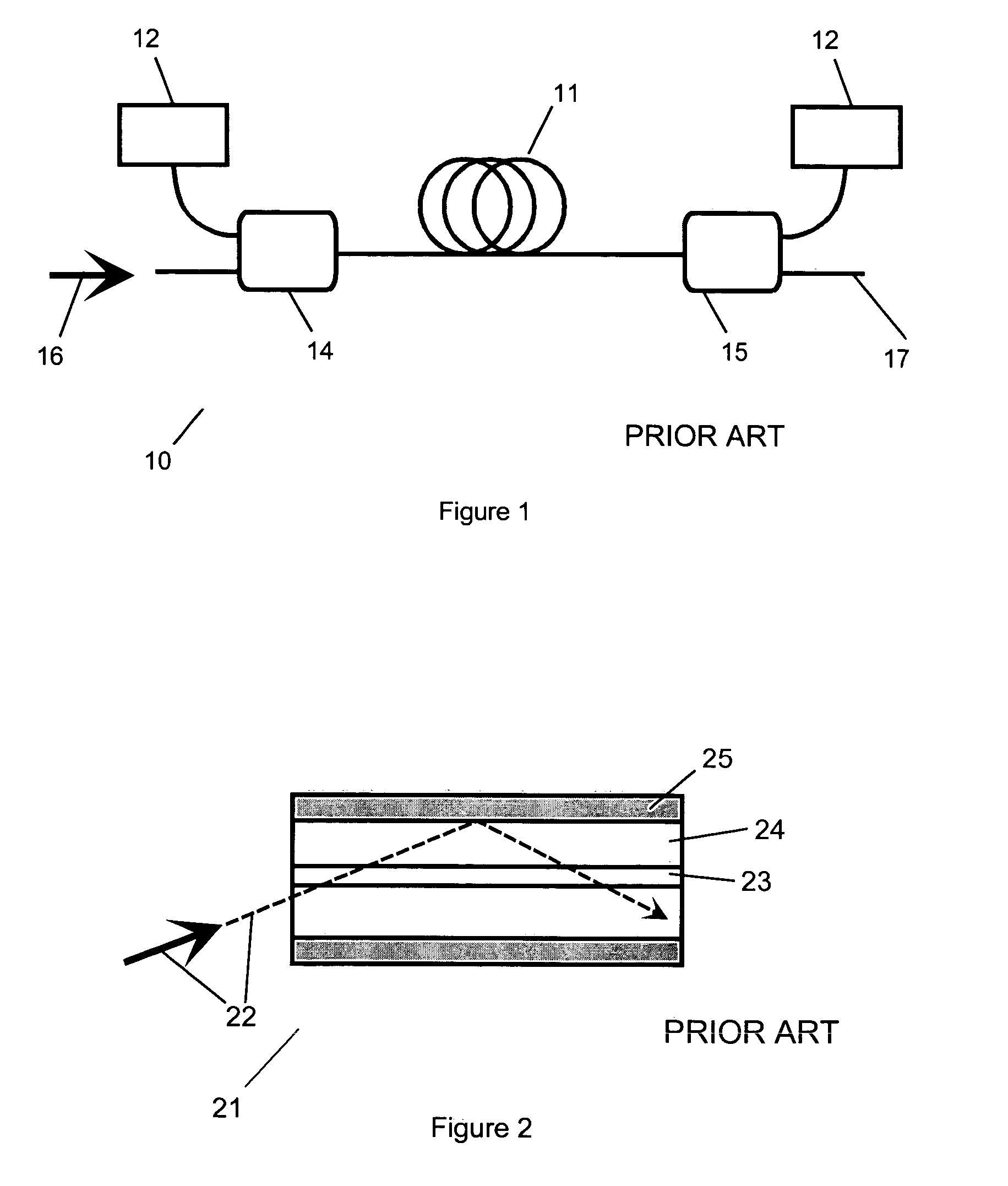
[0192] This Example is based on the configuration depicted in FIG. 32. The amplifying optical fibre 222 has an outer diameter (OD) of 200 μm and a core diameter of 10 μm. The core is single-moded at the signal wavelength and made of Er3+ / Yb3+-activated aluminosilicate glass. The pump absorption cross section at 980 nm is 20·10−25 cm2. The Yb3+concentration is 9000 particles per million (ppm). A 10 m long fibre absorbs ˜90% of launched pump power. The pump power is provided by 4 laser diodes with rated output power of 2 W. Using the simple launching scheme shown in FIG. 32 one can launch nearly 90% of pump power into the fibre amplifier

[0193] Assuming 35% efficiency the saturated output power of the example is in the region of 2.5 W. In many applications however required output power is 1 W which can be achieved with only 2.9 to 3 W of pump power, i.e. by using only two pump diodes. Thus by down-rating all four pump diodes to 800 mW one can achieve the required level of the output p...

example ii

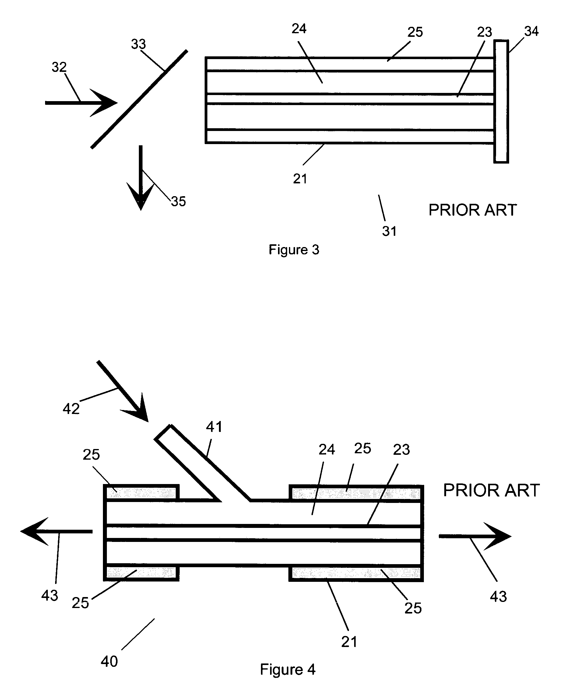
[0194] This Example is a mode-locked cladding pumped fibre laser with repetition rate frequency in the region of 50-200 MHz. The laser is based on the two fibre arrangement shown in FIG. 40. The amplifying optical fibre has an OD of 80 μm, core diameter of 15 μm and signal NA of 0.07. The core is single-moded at the signal wavelength and made of Yb3+-activated aluminosilicate glass. The pump absorption cross section at 980 nm is 20 X·10−25 cm2, which implies an Yb3+concentration of 1000 particles per million (ppm). A 1 m long fibre absorbs approximately 90% of launched pump power. The pump power is provided by 2 laser diodes with rated output power of 2 W.

[0195] With an appropriate mode-locking technique (either passive or active) the laser is capable of generating 1 ps pulses at repetition rate of 100 MHz and average power of 1 W and peak power in excess of 10 kW. Mirrors 401 form an optical resonator for the signal.

[0196] An advantage of using this configuration is that the sign...

example iii

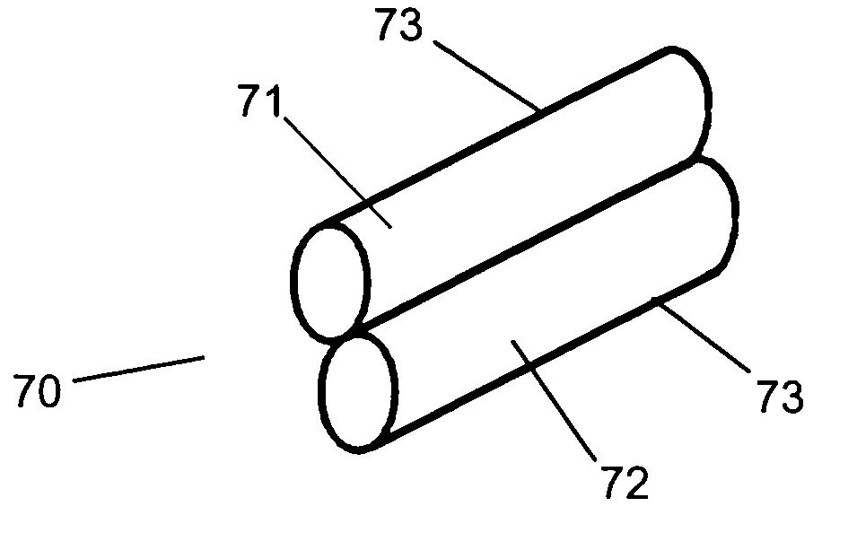
[0197] This Example is a multi-fibre arrangement including two or more pump diodes pumping simultaneously several amplifying optical fibres as shown in FIGS. 33 to 36. The amplifying optical fibres have an outer diameter (OD) of 100 μm and a core diameter of 10 μm. The core is single-moded at the signal wavelength and made of Er3+ / Yb3+-activated aluminosilicate glass. The pump absorption cross section at 980 nm is 20·10−25 cm2, which implies an Yb3+concentration of 9000 particles per million (ppm). A 5 m long fibre absorbs approximately 90% of launched pump power. The pump power is provided by 4 laser diodes with rated output power of 2 W. Using the simple launching scheme shown in FIG. 6 one can launch nearly 90% of pump power into the fibre amplifier. Assuming 35% efficiency the saturated output power of the Example is in the region of 1 W from each channel. It should be understood that total amount of output power available from all channels remains approximately the same so incr...


PUM

PropertyMeasurementUnit
Lengthaaaaaaaaaa
Diameteraaaaaaaaaa
Melting pointaaaaaaaaaa

Abstract

An optical fibre arrangement has at least two optical fibre sections, each optical fibre section defining an outside longitudinally extending surface. The outside longitudinally extending surfaces are in optical contact with each other. The invention further provides for an amplifying optical device have an optical fibre arrangement as just described, and a pump source. The amplifying optical device is configured such that the pump source illuminates the amplifying optical fibre. A amplifying arrangement is also disclosed. The amplifying arrangement includes a plurality of amplifying optical devices as just described, and each amplifier also has at least one input fibre and a first multiplexer connected to the input fibre. Each amplifier is configured such that at least one of the amplifying optical fibres is connected to the first multiplexer. The amplifying arrangement also has a second multiplexer connected to each of the first multiplexers.

Description

CROSS REFERENCE TO RELATED APPLICATIONS [0001] This application claims priority under 35 U.S.C. § 119 to patent applications serial numbers 9910165.1, filed in the United Kingdom on Apr. 30, 1999; and 9911958.8, filed in the United Kingdom on May 21, 1999 and which claims priority to United Kingdom patent application serial number 9910165.1; and 9917594.5, filed in the United Kingdom on Jul. 27, 1999. FIELD OF THE INVENTION [0002] This invention relates to an optical fibre arrangement, optical fibre lasers and optical fibre amplifiers. BACKGROUND OF THE INVENTION [0003] There is a demand for optical amplifiers that can output powers of 1W or greater, can amplify many wavelength channels simultaneously with low cross-talk and low inter-channel interference, and can do so with high reliability and low cost per wavelength channel. [0004] In many applications such as dense wavelength division multiplexing (WDM) transmission systems and satellite communications, optical amplifiers and tr...

Claims


Application Information

Patent Timeline
IPC IPC(8): C03B37/027C03B37/028C03B37/075C03C13/04G02B6/02G02B6/122G02B6/28G02B6/34H01S3/067H01S3/094H01S3/23
CPCB82Y20/00Y10T29/49885C03B37/028C03B37/075C03C13/046C03C2213/04G02B6/02347G02B6/1225G02B6/2835H01S3/06708H01S3/06758H01S3/094003H01S3/094019H01S3/2383C03B37/027
Inventor GRUDININ, ANATOLY BORISOVICHPAYNE, DAVE NEILTURNER, PAUL WILLIAMNILSSON, LARS JOHAN ALBINSSONZERVAS, MICHAEL NICKOLAOSIBSEN, MORTENDURKIN, MICHAEL KEVAN
Owner SPI LASERS UK
Why Eureka
Try Eureka