Chamber cleaning via rapid thermal process during a cleaning period

a technology of rapid thermal process and chamber cleaning, which is applied in the direction of chemical vapor deposition coating, coating, chemical apparatus and processes, etc., can solve the problems of unreliable processes, defective substrates, undesired residues deposited in or around exhaust channels, etc., to improve the surface temperature uniformity of chamber parts, increase the temperature of chamber parts, and improve the effect of chamber parts temperatur

Inactive Publication Date: 2005-05-26
SUN SHENG
View PDF20 Cites 263 Cited by
  • Summary
  • Abstract
  • Description
  • Claims
  • Application Information

AI Technical Summary

Benefits of technology

[0017] In another embodiment of the present invention there is provided a method for cleaning a process chamber, comprising the steps of introducing at least one precursor gas to the process chamber; applying a plasma to the precursor gas in the process chamber, wherein the plasma activates the precursor gas to generate reactive species; and employing a rapid heating module located in the process chamber, wherein the rapid heating module increases the temperature of chamber parts and improves the surface temperature uniformity of chamber parts when the module is turned on, thereby assisting the cleaning activity of the reactive species such that the process chamber is cleaned.
[0018] In another embodiment of the present invention there is provided a method for cleaning a process chamber, comprising the steps of introducing at least one halogen-containing gas to the process chamber; applying a plasma to the halogen-containing gas in the process chamber, wherein the plasma activates the halogen-containing gas to generate reactive species; and employing a rapid heating module located in the process chamber, wherein the rapid heating module comprises a high power lamp assembly, a resistive heater assembly, an inductive heater assembly, or a combination of two or more of the assemblies, wherein the rapid heating module increases the temperature of chamber parts and improves the surface temperature uniformity of chamber parts when the module is turned on, thereby assisting the cleaning activity of the reactive species such that the process chamber is cleaned.
[0019] In another embodiment of the present invention there is provided a method for cleaning a process chamber, comprising the steps of introducing at least one fluorine-containing gas to the process chamber; applying a plasma to the fluorine-containing gas in the process chamber, wherein the plasma activates the fluorine-containing gas to generate reactive species; and employing a rapid heating module located in the process chamber, wherein the rapid heating module comprises a high power lamp assembly placed at the bottom of the process chamber, a resistive heater assembly or an inductive heater assembly embedded in the chamber wall next to the liners, or a combination of two or more of the assemblies, wherein the rapid heating module increases the temperature of chamber parts and improves the surface temperature uniformity of chamber parts when the module is turned on, thereby assisting the cleaning activity of the reactive species such that the process chamber is cleaned.
[0020] In yet another embodiment of the present invention there is provided a method for cleaning a process chamber, comprising the steps of introducing at least one precursor gas to a remote chamber, wherein the remote chamber is connected to the interior of the process chamber; applying a plasma to the precursor gas in the remote chamber wherein the plasma activates the precursor gas to generate reactive species; introducing the reactive species to the process chamber; and employing a rapid heating module located in the process chamber, wherein the rapid heating module increases the temperature of chamber parts and improves the surface temperature uniformity of chamber parts when the module is turned on, thereby assisting the cleaning activity of the reactive species such that the process chamber is cleaned.
[0021] In yet another embodiment of the present invention there is provided a method for cleaning a process chamber, comprising the steps of introducing at least one halogen-containing gas to a remote chamber, wherein the remote chamber is connected to the interior of the process chamber; applying a plasma to the halogen-containing gas in the remote chamber wherein the plasma activates the halogen-containing gas to generate reactive species; introducing the reactive species to the process chamber; and employing a rapid heating module located in the process chamber, wherein the rapid heating module comprises a high power lamp assembly, a resistive heater assembly, an inductive heater assembly, or a combination of two or more of the assemblies, wherein the rapid heating module increases the temperature of chamber parts and improves the surface temperature uniformity of chamber parts when the module is turned on, thereby assisting the cleaning activity of the reactive species such that the process chamber is cleaned.
[0022] In yet another embodiment of the present invention there is provided a method for cleaning a process chamber, comprising the steps of introducing at least one fluorine-containing gas to a remote chamber, wherein the remote chamber is connected to the interior of the process chamber; applying a plasma to the fluorine-containing gas in the remote chamber wherein the plasma activates the fluorine-containing gas to generate reactive species; introducing the reactive species to the process chamber; and employing a rapid heating module located in the process chamber, wherein the rapid heating module comprises a high power lamp assembly placed at the bottom of the process chamber, a resistive heater assembly or an inductive heater assembly embedded in the chamber wall next to the liners, or a combination of two or more of the assemblies, wherein the rapid heating module increases the temperature of chamber parts and improves the surface temperature uniformity of chamber parts when the module is turned on, thereby assisting the cleaning activity of the reactive species such that the process chamber is cleaned.

Problems solved by technology

Undesirable deposition occurs elsewhere in the process apparatus, such as in the area between the gas mixing box and gas distribution manifold.
Undesired residues also may be deposited in or around the exhaust channel, the liners and walls of the process chamber during such processes.
Over time, failure to clean the residue from the process apparatus often results in degraded, unreliable processes and defective substrates.
The problem of impurities causing damage to the devices on the substrate is of particular concern with today's increasingly small device dimensions.
Unfortunately, such cleaning operations affect a substrate processing system's throughput in a variety of ways.
When a wet clean is performed, opening the process chamber and physically wiping the chamber's interior surfaces results in even more downtime because the process must subsequently be re-stabilized.
Additionally, frequent cleaning operations tend to increase wear on the process chamber components.
Unfortunately, exposure to plasmas created from such gases often causes the deterioration of process chamber components.
This increased wear can lead to component failure; thereby causing extended downtime, and adversely affecting processing system throughput.
The use of reactive gases in cleaning process chambers, however, also suffers from a further disadvantage.
The same radicals that provide desirable cleaning characteristics may themselves cause the formation of residues.
For example, the use of such gases can cause the accumulation of polymer residues, which also exhibit undesirable qualities.
Therefore, the prior art is deficient in the lack of effective means of cleaning a process chamber in chemical vapor deposition (CVD) or etching processes.
Specifically, the prior art is deficient in the lack of effective means of chamber cleaning via rapid thermal process during the cleaning period.

Method used


Image

  • Chamber cleaning via rapid thermal process during a cleaning period
  • Chamber cleaning via rapid thermal process during a cleaning period
  • Chamber cleaning via rapid thermal process during a cleaning period

Examples


example 1

Chamber Wall and Liner Temperature Measurement

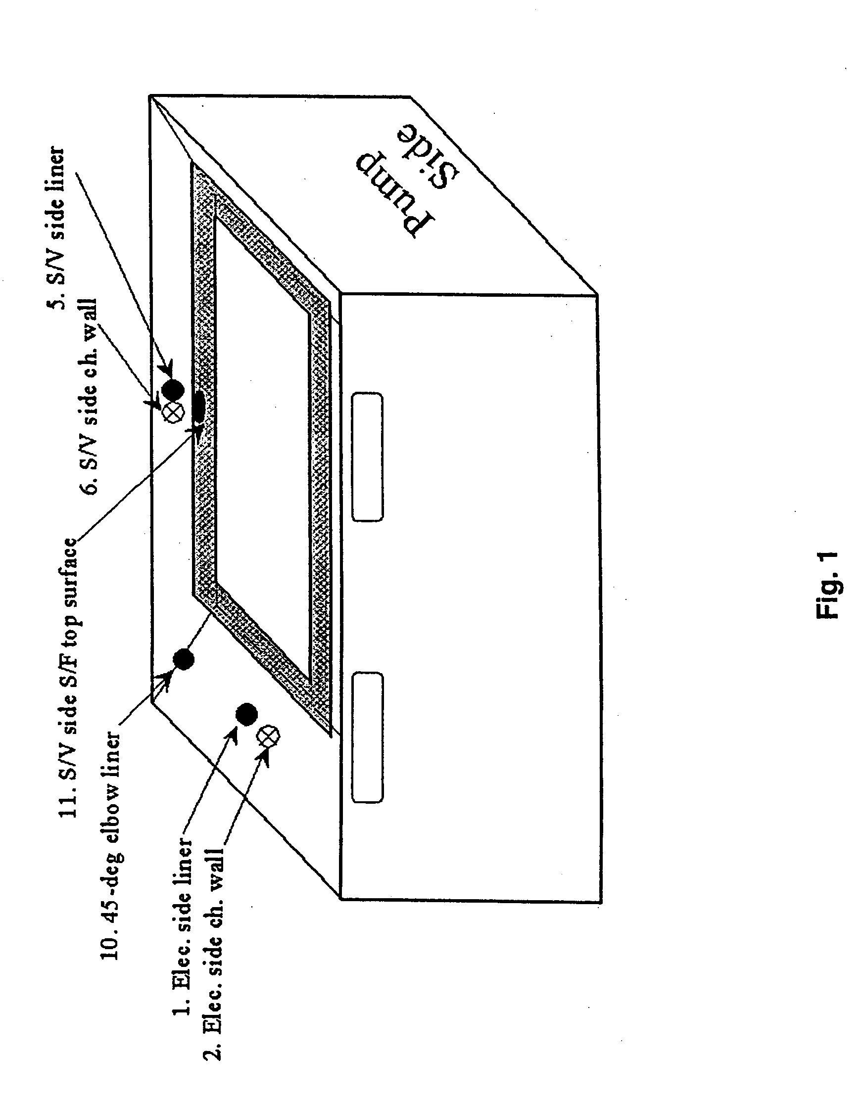
[0043] In AKT CVD-5500 chamber system, ⅛″ thick ceramic spacers were added between the liners and chamber wall to study heat transfer and liner temperature (FIG. 1). Eleven thermocouples (TCs) were installed, six of which survived (i.e., TC1, TC2, TC5, TC6, TC10 and TC11). The six surviving TCs were Kepton-taped to different places on the chamber wall, liners and shadow frame (for substrate clamping purpose).

[0044] TC1 was attached to the middle of the left-side liner, while TC2 was placed underneath on the chamber wall. Similarly, TC5 was attached to the middle of the slit valve side liner, while TC6 was embedded underneath on the chamber wall. TC10 was placed on the corner elbow-shaped liner, while TC11 was laid on the shadow frame top surface.

[0045] All the temperature readings were recorded at different process conditions though the susceptor temperature was maintained at 350 / 360° C. for inner / outer heater combination. With this ...

example 2

AKT Fat-Belly-Liner Chamber

[0049] In AKT CVD-5500 alpha (A) chamber, 45-degree liners were changed to Fat-Belly type on all sides except the window side (view limited). Table 3 shows the clean rate comparison between the original and Fat-Belly type 45-degree liners.

TABLE 3SiH4Dep. TimeDep. RateCln. TimeCln. Rate(sccm)(sec)(20 mm)(sec)(A / min)GHOrig. Liner6701801851486941Fat-Belly670180181348.7670145-degLinersAHOrig. Liner1310601250135769Fat-Belly1310110126320694745-degLiners

Dep.: deposition; Cln: clean; GH: high-deposition rate SiNx film; and AH: high-deposition rate amorphous silicon (α-Si) film.

[0050] It is shown that Fat-Belly 45-degree liners did achieve faster clean rate in the α-Si cleaning (−20% for AH) case, but in the SiN (GH) case, the clean rate is the same (Table 3). Additionally, Fat-Belly 45-degree liners achieved ˜2-3% better deposition uniformity in α-Si and SiN films. The fat-belly liners are modified liners which are in closer proximity to the active heating de...

example 3

Rapid Thermal Process

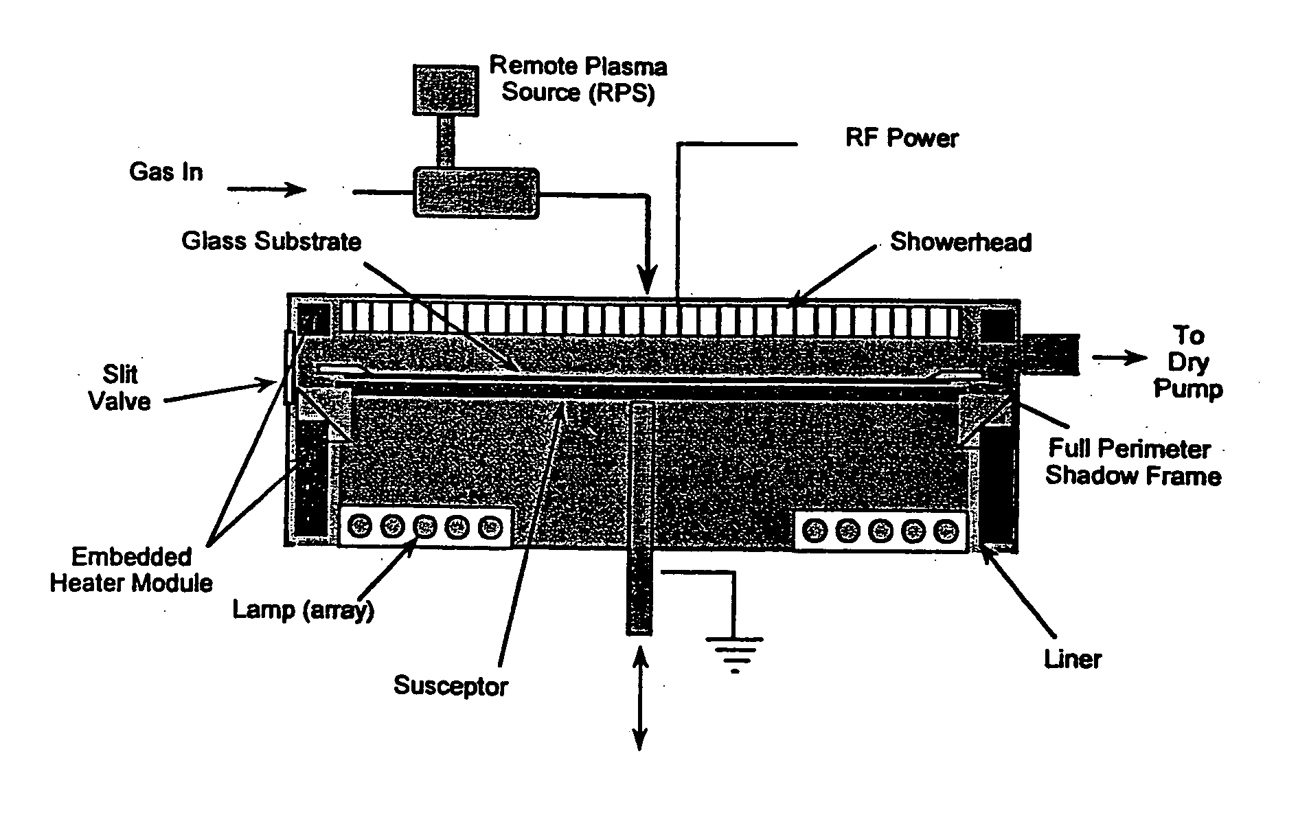
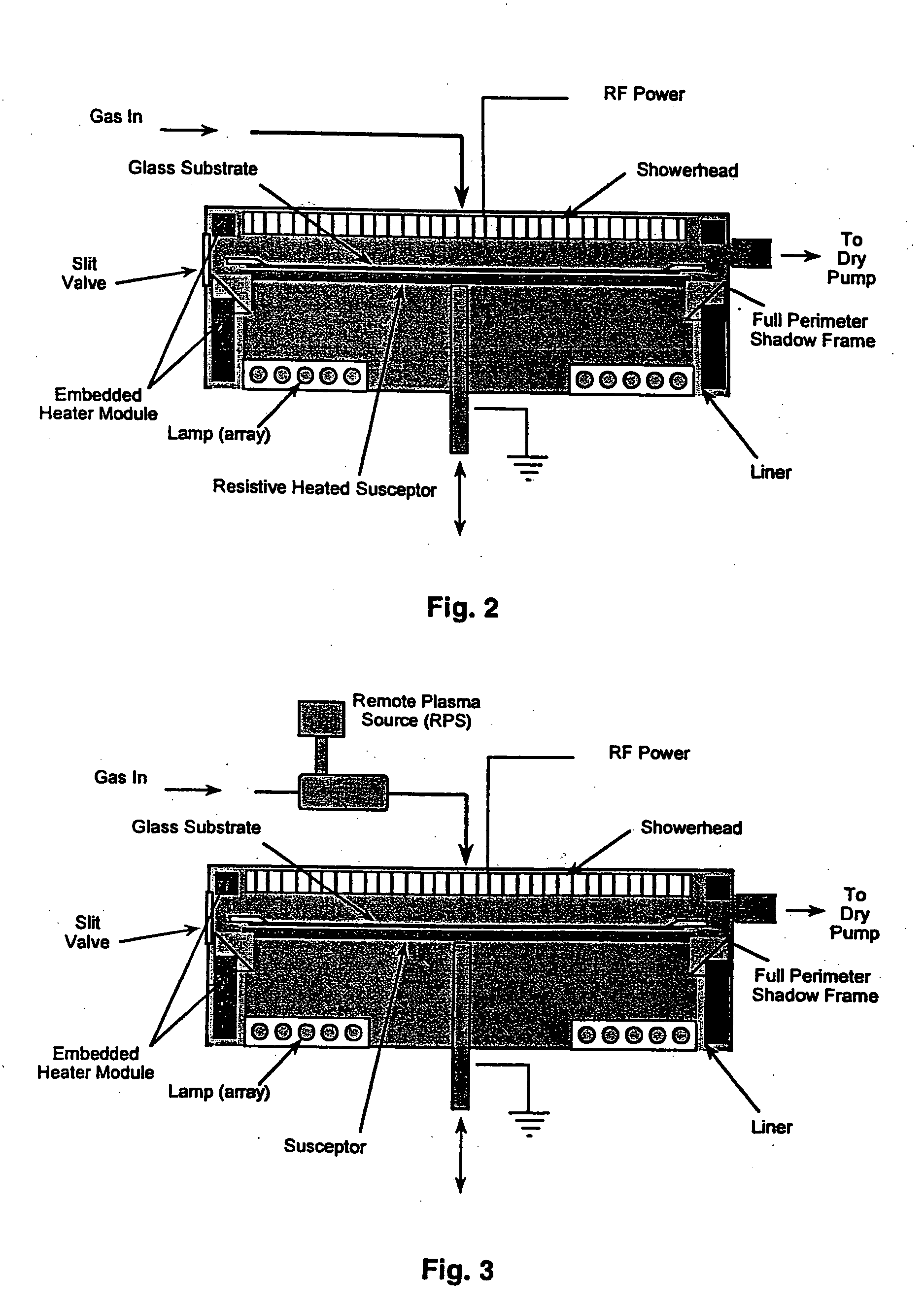
[0052] In AKT PECVD systems, a significant amount of cleaning time is spent cleaning the chamber peripheral parts, such as liners which have the lower surface temperatures due to the close proximity to the wall. The rapid heating module can be a high power lamp placed at the bottom of the chamber, or a resistive heater embedded in the wall next to the liner, or a combination of both. It is contemplated that an inductive heater may also be embedded in the wall next to the liner and may be used singly or in combination with the high power lamp and / or the resistive heater.

[0053] When the module heats up, liners and other chamber parts experience a higher surface temperature, which facilitates faster cleaning of the film residues. As was shown in Table 1, a higher surface temperature results in a higher dry etch rate; by extension, further raising the surface temperature of the chamber parts through the action of an RTP module will increase the cleaning rate.

[00...


PUM

PropertyMeasurementUnit
temperatureaaaaaaaaaa
pressureaaaaaaaaaa
RF poweraaaaaaaaaa

Abstract

A method for cleaning a process chamber, comprising the steps of introducing at least one cleaning gas to the process chamber; and employing a rapid heating module located in the process chamber, wherein the rapid heating module increases the temperature of chamber parts and improves the surface temperature uniformity of chamber parts when the module is turned on, thereby assisting the cleaning activity of the cleaning gas such that the process chamber is cleaned.

Description

CROSS-REFERENCE TO RELATED APPLICATIONS [0001] This application is a continuation of co-pending U.S. patent application Ser. No. 09 / 866,225, filed May 24, 2001, which patent application is herein incorporated by reference.BACKGROUND OF THE INVENTION [0002] 1. Field of the Invention [0003] The present invention relates generally to the field of semiconductor manufacturing. More specifically, the present invention relates to an improved chamber cleaning method via a rapid thermal process during the cleaning period. [0004] 2. Description of the Related Art [0005] An important way to improve quality and overall efficiency in fabricating devices is to clean the chamber effectively and economically. During processing, reactive gases released inside the process chamber form layers such as silicon oxides or nitrides on the surface of a substrate being processed. Undesirable deposition occurs elsewhere in the process apparatus, such as in the area between the gas mixing box and gas distribut...

Claims


Application Information

Patent Timeline
Patent Type & Authority Applications(United States)
IPC IPC(8): B08B7/00C23C16/44
CPCC23C16/4405B08B7/00
Inventor SUN, SHENG
Owner SUN SHENG
Why Eureka
Try Eureka