
Method of fabricating a semiconductor device

a semiconductor device and manufacturing method technology, applied in the direction of semiconductor devices, electrical devices, transistors, etc., can solve the problems of destroying all pixels of one column (or one row), complicated drive circuit for driving all the pixels, and forming many tfts

Inactive Publication Date: 2005-05-26
SEMICON ENERGY LAB CO LTD
View PDF62 Cites 56 Cited by
  • Summary
  • Abstract
  • Description
  • Claims
  • Application Information

AI Technical Summary

Benefits of technology

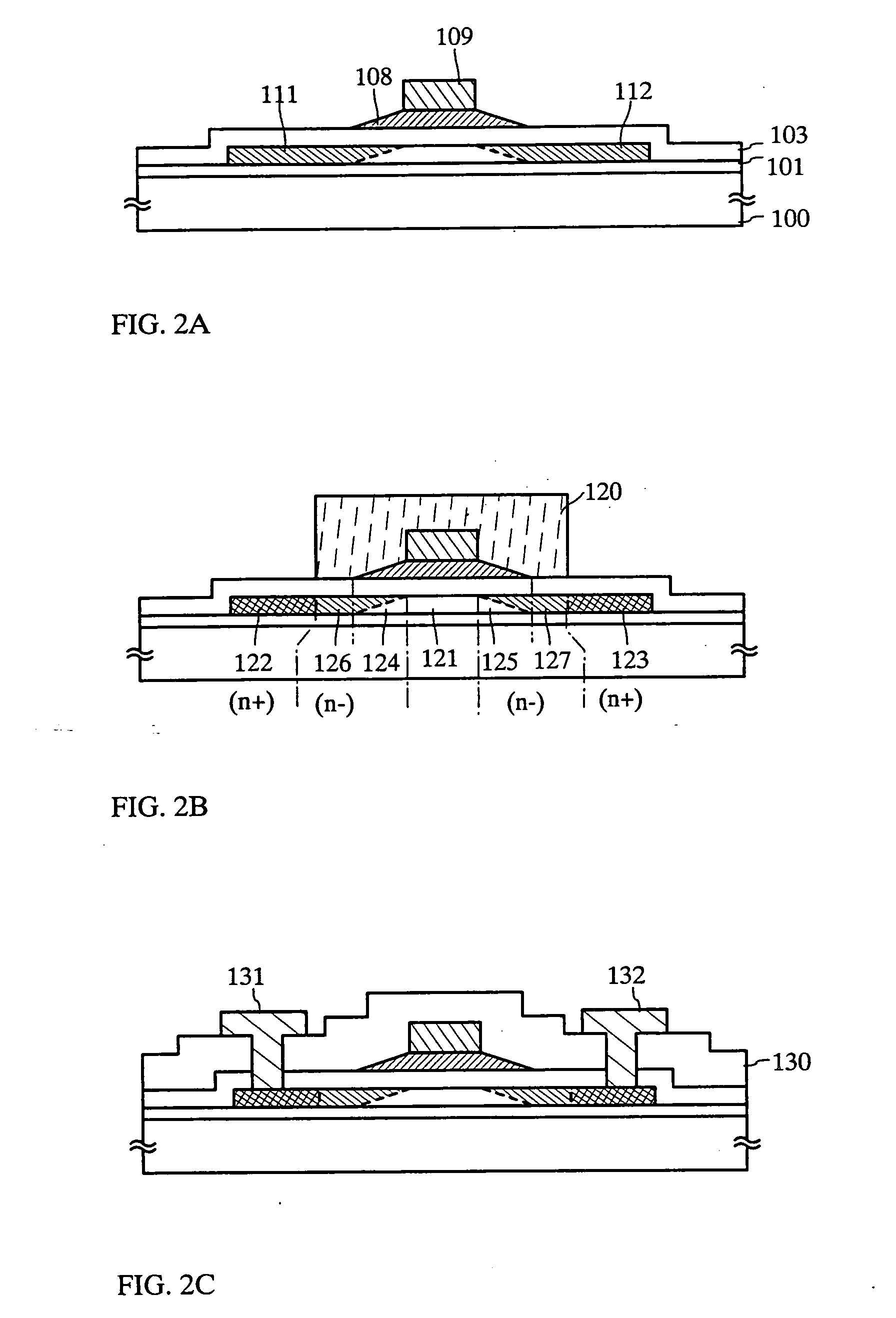
The present invention provides a thin film transistor (TFT) with improved performance. The TFT has a reduced off current and high hot carrier resistance. This results in a highly reliable semiconductor device that includes this TFT. The TFT has a unique structure with two kinds of impurity regions, namely, a first impurity region and two low concentration impurity regions. The first impurity region acts as a source or drain region and the second and third impurity regions have a lower concentration and act as high resistance regions. The second impurity region overlaps with a gate electrode and increases hot carrier resistance, while the third impurity region prevents an off current from increasing. The gate electrode has a linearly decreased thickness from its center flat portion to the outside, which results in a gradient of impurity concentration. The TFT has the same reliability as a MOSFET and is suitable for use in semiconductor devices.

Problems solved by technology

A driver circuit for driving all the pixels is formed of very complicated and numerous TFTs.
Particularly, if an abnormality occurs in the driver circuit, there occurs a bad state called a linear defect in which all pixels of one column (or one row) are destroyed.
However, a TFT using a polysilicon film is generally considered to be inferior in reliability to a MOSFET (transistor formed on a single crystal semiconductor substrate) used for an LSI or the like.
Such a view becomes strong that it is difficult to form an LSI circuit by TFTs unless this weak point is overcome.
However, the GOLD structure disclosed in the paper has a problem that an off current (current flowing when a TFT is in an off state) becomes large as compared with a normal LDD structure, and a countermeasure for that has been required.

Method used


Image

  • Method of fabricating a semiconductor device
  • Method of fabricating a semiconductor device
  • Method of fabricating a semiconductor device

Examples


embodiment mode 1

[Embodiment Mode 1]

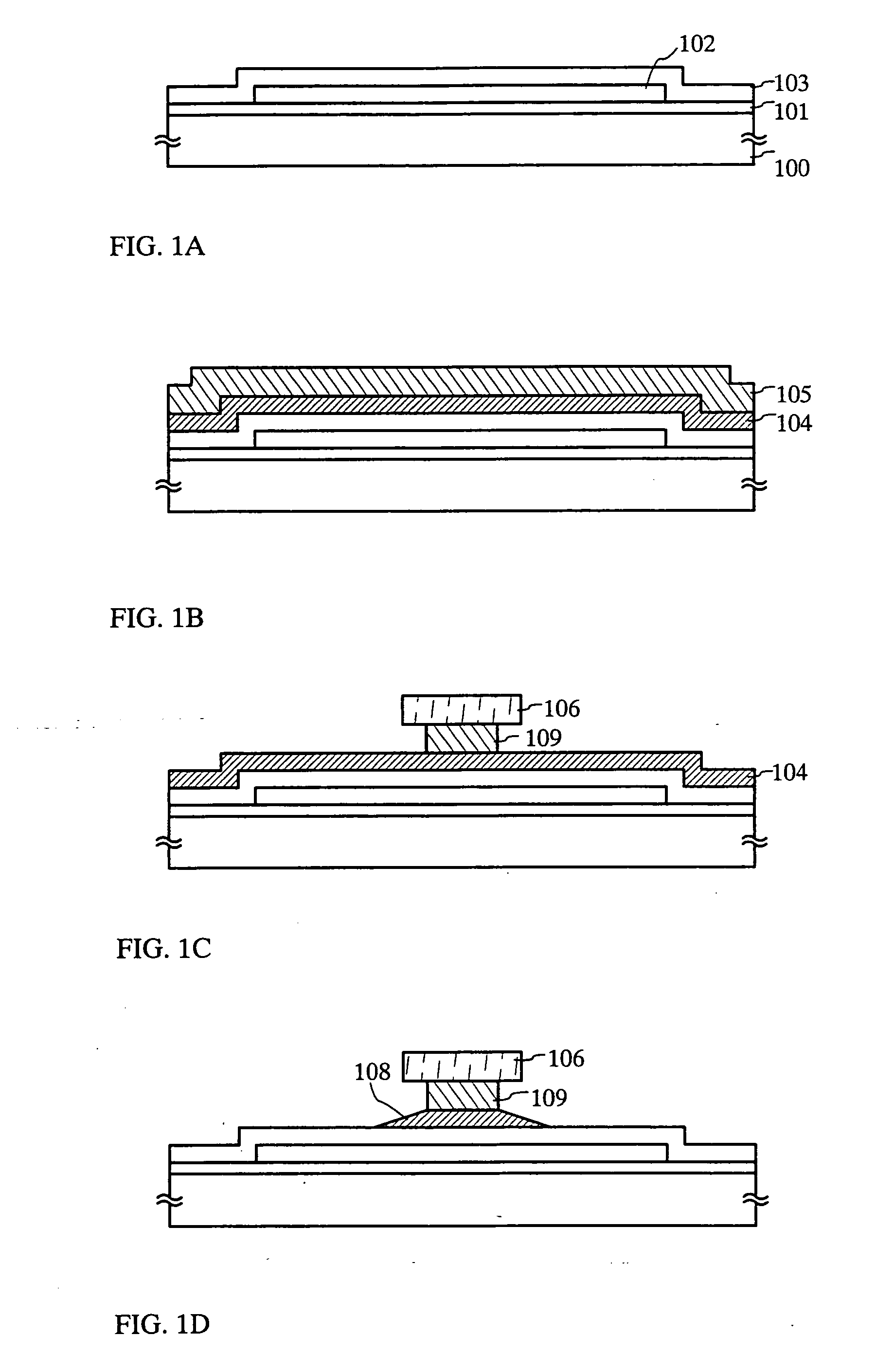
[0072] In this embodiment mode, the present invention is applied to a TFT. Fabricating steps in this embodiment mode will be described with reference to FIGS. 1A to 4D.

[0073] First, an under film 101 is formed on the entire surface of a substrate 100, and an island-like semiconductor layer 102 is formed on the under film 101. An insulating film 103 which becomes a gate insulating film is formed on the entire surface of the substrate 100 to cover the semiconductor layer 102 (FIG. 1A).

[0074] As the substrate 100, a glass substrate, a quartz substrate, a crystalline glass substrate, a stainless substrate, or a resin substrate of polyethylene terephthalate (PFT) etc. may be used.

[0075] The under film 101 is a film for preventing an impurity such as a sodium ion from diffusing from the substrate to the semiconductor layer 102 and for increasing the adhesion of a semiconductor film formed on the substrate 100. As the under film 101, a single-layer or multi-layer film...

embodiment mode 2

[Embodiment Mode 2]

[0115] Fabricating steps of a TFT of this embodiment mode 2 will be described with reference to FIGS. 5A to 5C and FIGS. 6A to 6C. This embodiment mode is a modified example of the embodiment mode 1, in which the structure of a gate electrode (gate wiring line) is modified, and another main structure is the same as the embodiment mode 1.

[0116] Although the gate electrode in the embodiment mode 1 has such a structure that two gate electrodes with different widths are laminated, in this embodiment mode, the upper second electrode is omitted, and the gate electrode is formed of only a first gate electrode having a taper portion.

[0117] First, an under film 141 is formed on the entire surface of a substrate 140, and an island-like semiconductor layer 142 is formed on the under film 141. An insulating film 143 which becomes a gate insulating film is formed on the entire surface of the substrate 140 to cover the semiconductor layer 142 (FIG. 5A).

[0118] A conductive fi...

embodiment mode 3

[Embodiment Mode 3]

[0132] Fabricating step of a TFT of this embodiment mode will be described with reference to FIG. 7. This embodiment mode is also a modified example of the embodiment mode 1, in which the structure of a gate electrode (gate wiring line) is modified, and another main structure is the same as the embodiment mode 1. Incidentally, in FIG. 7, the same reference numerals as FIGS. 1 and 2 designate the same structural elements.

[0133] Similarly to the embodiment mode 1, although a gate electrode of this embodiment mode 3 has such a structure that a first gate electrode 168 and a second gate electrode 169 are laminated to each other, this embodiment mode is an example in which a side of the first gate electrode 168 is not made taper-shaped. In this embodiment mode, the portion of the first gate electrode 168 extending from the side of the second gate electrode 169 to the outside also has an almost constant film thickness.

[0134] A channel formation region 161, n+-type fir...


PUM


Abstract

There is provided a thin film transistor having improved reliability. A gate electrode includes a first gate electrode having a taper portion and a second gate electrode with a width narrower than the first gate electrode. A semiconductor layer is doped with phosphorus of a low concentration through the first gate electrode. In the semiconductor layer, two kinds of n−-type impurity regions are formed between a channel formation region and n+-type impurity regions. Some of the n−-type impurity regions overlap with a gate electrode, and the other n−-type impurity regions do not overlap with the gate electrode. Since the two kinds of n−-type impurity regions are formed, an off current can be reduced, and deterioration of characteristics can be suppressed.

Description

BACKGROUND OF THE INVENTION [0001] 1. Field of the Invention [0002] The present invention relates to a thin film transistor (hereinafter referred to as a “TFT”) and a semiconductor device including a circuit constituted by thin film transistors. The present invention also relates to, as the semiconductor device, an electro-optical device typified by, for example, a liquid crystal panel, and an electronic equipment including such an electro-optical device as a part. Incidentally, the term “semiconductor device” in this specification indicates any devices functioning by using semiconductor characteristics, and an electro-optical device, a semiconductor circuit, and an electronic equipment are also semiconductor devices. [0003] 2. Description of the Related Art [0004] In recent years, attention has been paid to an active matrix type liquid crystal display device in which its circuit is constituted by TFTs using polysilicon films. This device controls an electric field applied to a liqu...

Claims


Application Information

Patent Timeline
Patent Type & Authority Applications(United States)
IPC IPC(8): H01L21/28H01L21/336H01L21/77H01L21/84H01L27/12H01L29/423H01L29/786
CPCH01L21/28114H01L29/42384H01L29/66598H01L29/66757H01L29/78621H01L27/1214H01L29/66492H01L27/1222H01L2029/7863H01L27/12H01L29/78627H10K59/12H10K59/1213H10K50/8445H10K59/123H10K59/10H01L29/78675H01L29/78696
Inventor YAMAZAKI, SHUNPEI
Owner SEMICON ENERGY LAB CO LTD
Learn More