
Secret key distribution method and secret key distribution system

Inactive Publication Date: 2005-05-26
KK TOSHIBA
View PDF3 Cites 27 Cited by
  • Summary
  • Abstract
  • Description
  • Claims
  • Application Information

AI Technical Summary

Benefits of technology

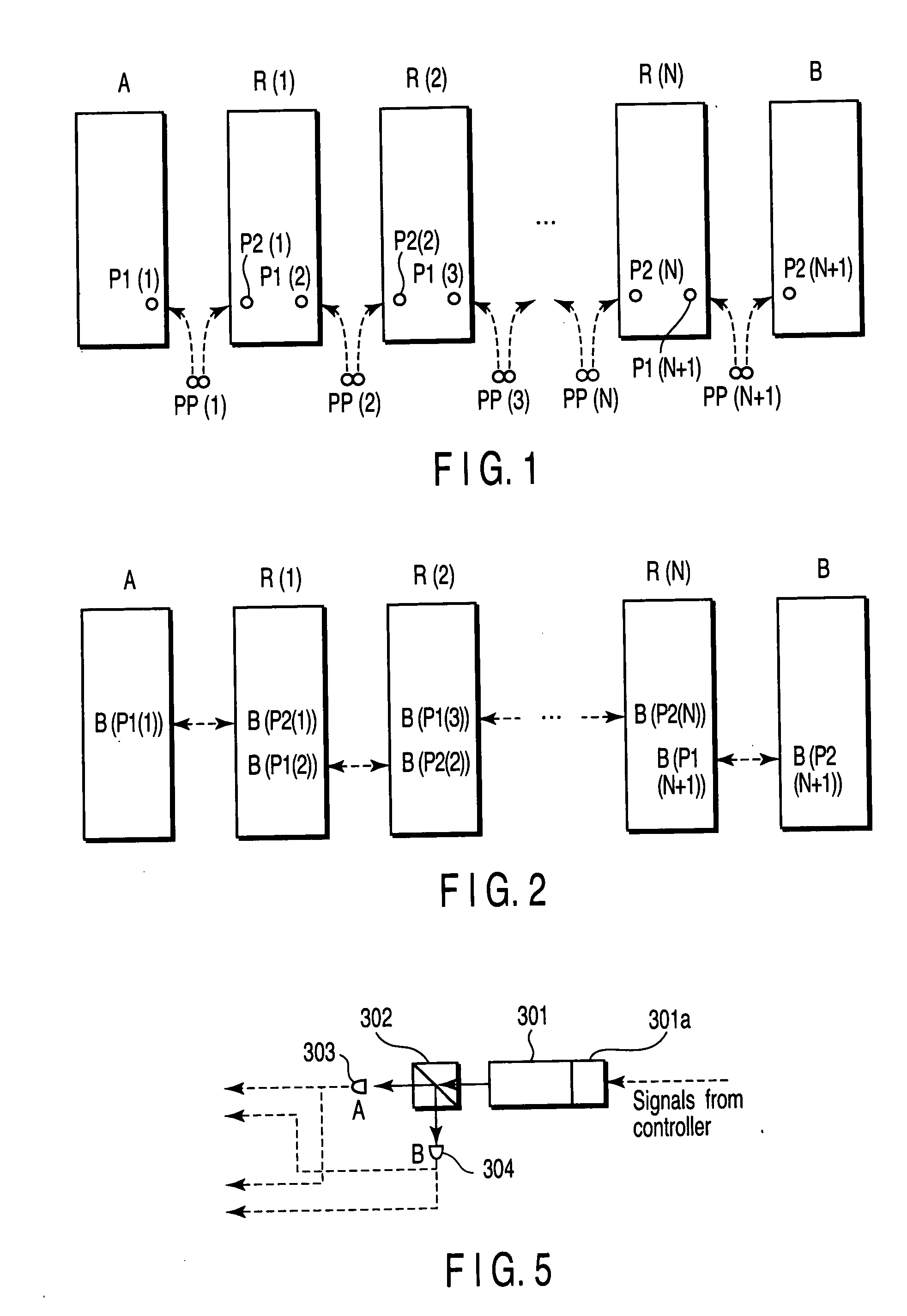
[0012] An object of the present invention is to provide a high-security secret key distribution method and system which realizes long-distance communication without decrease of the number of secret keys due to relaying, which is advantageous for increasing a transmission rate because of absence of waste of bits, and which contains a mechanism for generating high-quality random numbers efficiently.

Problems solved by technology

The property of making duplication impossible offers a security advantage, but on the other hand, it means that amplification is impossible even if the photon is attenuated in a communication path, such as an optical fiber.
Since relaying cannot be effected by simple signal amplification, the distance available for quantum cryptography communication is limited to the distance that a generated photon would be transmitted without attenuation.
However, this method always requires quantum communication whenever cryptography communication is desired.
When a secret key distribution method without an entanglement frequently tested at present is tried directly in quantum communication between relay stations in distributing a long-distance communication secret key by way of classic relay stations, the following problem arises: that is, the number of secret keys decreases at a rate of 1 / 2 or less each time relaying is performed, regardless of the relay distance, making the relaying meaningless.
In this method, even if information about the bases used by the sender and receiver has leaked out, since the photon has already passed through the quantum transmission path (e.g., an optical fiber), such a type of eavesdropping that extracting the photon from the quantum transmission path and detecting the photon using the base to obtain information about the secret key and then generating a photon in the same quantum state and making the photon return to the quantum transmission path, cannot be done.
Therefore, the problem is that a high-quality and efficient random number-generating mechanism has to be built in.
Further, since it is necessary to use secret keys repeatedly, it is difficult to increase the transmission rate, unless the number of bits discarded wastefully is reduced.
As described above, when a secret key for long-distance communication is to be distributed by repeating secure quantum communication between relay stations in the case where security in the relay stations would be secured, there arise a problem that the number of secret keys is exponentially decreased each time relaying is performed, or a large number of high-quality random numbers must be generated efficiently.
However, a simple of solving these problems has not been known.

Method used


Image

  • Secret key distribution method and secret key distribution system
  • Secret key distribution method and secret key distribution system
  • Secret key distribution method and secret key distribution system

Examples


embodiments

[0067] Hereinafter, embodiments of the present invention will be described referring to the accompanying drawings.

first embodiment

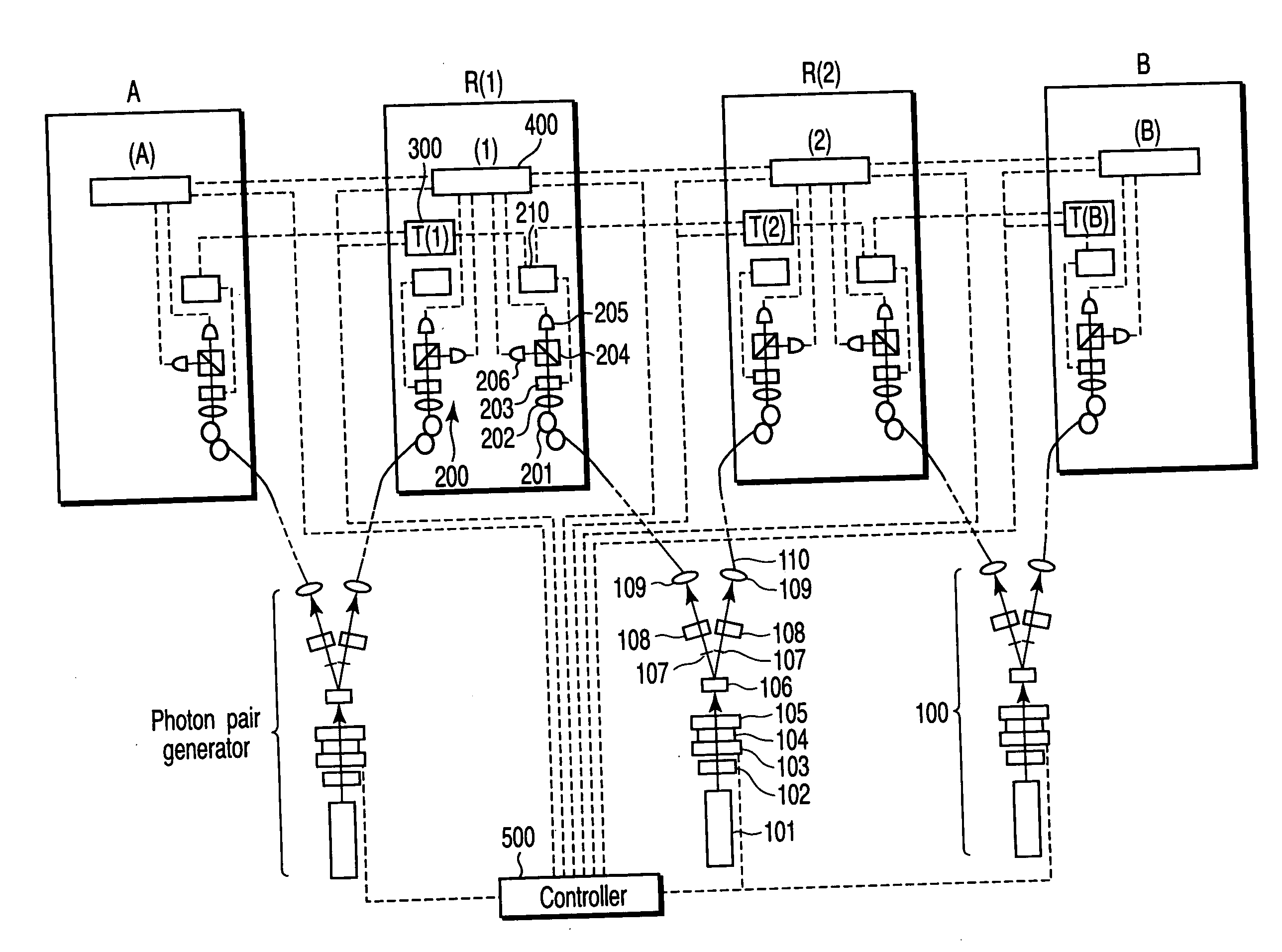
[0068]FIG. 4 shows the construction of the secret key distribution system according to a first embodiment of the present invention. FIG. 4 shows a case where two relay stations R(1), R(2) are located between sites A and B. Suppose these four sites A, R(1), R(2) and B are arranged in a straight line at intervals of 1 km. A photon pair generator 100 for generating photon pairs connected through an entanglement is provided between A and R(1), between R(1) and R(2), and between R(2) and B. Let these photon pair generators be PPG(1), PPG(2), and PPG(3).

[0069] Each of the photon pair generators 100 includes an argon ion laser 101 with a wavelength of 351.1 nm, an ND filter 102, a shutter 103 using an electro-optic modulator, a half-wave plate 104, a quarter-wave plate 105, a 0.6-mm-thick nonlinear BBO (β-barium borate) crystal 106, an iris diaphragm 107, a half-wave plate 108, and a lens 109.

[0070] The argon ion laser 101 emits light. The ND filter 102 adjusts intensity of the light. Th...

second embodiment

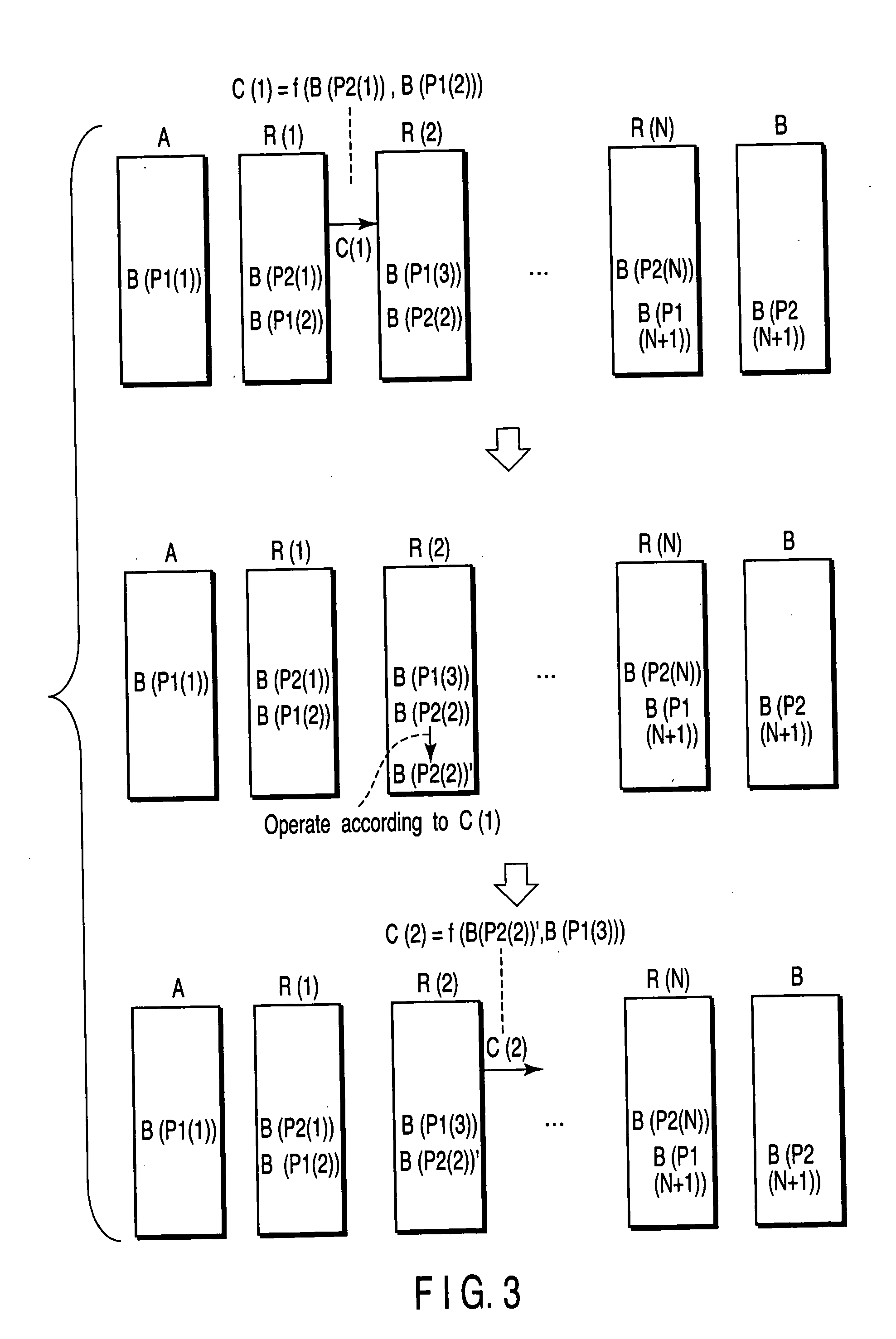
[0083] A sequence of numbers “0, 1, 1, 0, 1, 1, 0, 0, 0, 1” was stored beforehand as random number sequence BA(r) (r=1, 2, . . . , 10) in the data acquisition-calculation-storage unit (A) in the first embodiment. In the q-th operation to obtain correlated bits in A and B, the data acquisition-calculation-storage unit (A) was configured as follows. That is, the data acquisition-calculation-storage unit (A) is so configured that, if BA(q) and B(P1(1)) differ from each other, it sends to the data acquisition-calculation-storage unit (1) an instruction that “set B(P2(1)) as it is to B(P2(1))′ without inverting the bit of B(P2(1))”, and that, if BA(q) and B(P1(1)) are the same, it sends to the data acquisition-calculation-storage unit (1) an instruction that “invert the bit of B(P2(1)) and set it to B(P2(1))′”. In addition, as in the first embodiment, the data acquisition-calculation-storage unit (1) is so configured that, if B(P2(1))′ and B(P1(2)) are the same, it sends to the data acqu...


PUM


Abstract

In the method of the present invention, one of each pair of photons connected through entanglement is distributed to a transmitting station, relay stations and a receiving station. After the photons reach secure sites, such as the relay stations, a base for detecting photons is determined between adjacent sites, and then photons are detected in each site, which makes it possible to obtain a secret key used for secure information transmission between relay stations using bases coincide with each other every time. Also, in the present invention, a high-quality random number sequence serving as a secret key is automatically generated in a physical manner every time by detecting a superposition state of an entanglement and procedures corresponding to those in which a secret key itself is transmitted in a form of a quantum cryptogram are performed.

Description

CROSS-REFERENCE TO RELATED APPLICATIONS [0001] This application is based upon and claims the benefit of priority from prior Japanese Patent Application No. 2003-370922, filed Oct. 30, 2003, the entire contents of which are incorporated herein by reference. BACKGROUND OF THE INVENTION [0002] 1. Field of the Invention [0003] The present invention relates to a secret key distribution method and a secret key distribution system that combine quantum communication in which information is put on a quantum state of a photon, making it almost impossible to eavesdrop, with a classic relay that temporarily converts the information transmitted in quantum communication into classic information and then transmits the relayed information in quantum communication again. [0004] 2. Description of the Related Art [0005] In quantum cryptography communication, a quantum state of a photon is used to carry information so as to distribute a secret key safely, making use of the fact that duplication of the ...

Claims


Application Information

Patent Timeline
IPC IPC(8): G02F2/00G02F1/39H04L9/08H04L9/12
CPCH04L9/0855
Inventor ICHIMURA, KOUICHISHIOKAWA, NORITSUGUFUJII, MIKIOTORII, KENTAROOHKUMA, KENJI
Owner KK TOSHIBA
Learn More