Phase-change optical recording medium

a technology of optical recording medium and phase change, which is applied in the direction of instruments, photomechanical equipment, and thermography. it can solve the problems of information in a certain track deteriorating, so-called cross-erase problems, and errors in the stage of converting the obtained signal into digital data

Inactive Publication Date: 2005-05-26
KK TOSHIBA
View PDF7 Cites 39 Cited by
  • Summary
  • Abstract
  • Description
  • Claims
  • Application Information

AI Technical Summary

Problems solved by technology

However, where the recording marks are close to each other, the obtained signal has low amplitude, with the result that errors tend to occur in the stage of converting the obtained signal into digital data.
In this method, however, a so-called cross-erase problem is generated.
Specifically, if the track pitch is made substantially equal to or smaller than a light beam size, the information in a certain track deteriorates when writing or erasure is performed on the adjacent track.
The cross-erase problem is generated partly because the mark on the target track is irradiated directly with the edge of the laser beam on the adjacent track, and partly because heat generated in the recording stage flows into the adjacent track so as to raise the temperature of the mark on the adjacent track and, thus, to deform the mark.
In the case of such a thin recording film, the retention time required for the crystallization is prolonged, with the result that the recording mark fails to be erased completely at the normal recording speed (reduction of erasure rate).
However, in order to compensate for the crystallizing speed that is reduced in accordance with the decrease in the thickness of the recording film, it is insufficient to simply take a measure such as a change in the composition of the recording film material.
However, as a result of extensive research conducted by the present inventors, it has been found that cross-erase is generated in the combination of the thin recording film having a thickness of 5 to 7 nm and the conventional interface film such as GeN and, thus, it is difficult to sufficiently shorten the track pitch.
It has also been found that any of the interface films referred to above has a high extinction coefficient in the wavelength of the laser light (405 nm) used in the next-generation high-density optical disc, incurring a very high optical loss.
In contrast, the recording medium in which the interface film is not arranged permits suppressing the recrystallization of the molten portion so as to suppress the cross-erase to a low level, but has an insufficient erasure rate.
However, one of the factors for inhibiting the high-speed recording in the phase-change optical recording medium is a problem that the information fails to be erased completely when crystallization is performed in the overwriting stage by a laser beam at a relatively low erasure level, i.e., the problem of the insufficient erasure rate.
To be more specific, since the recording mark passes through the laser spot at a high speed, it is difficult to maintain the recording mark for a sufficiently long time in temperature range within which the crystallization can be performed, with the result that the information fails to be erased completely.
It should be noted that the use of the interface film noted above requires makes it necessary to melt the region larger than required, resulting in promotion of the cross-erase, which brings about an adverse effect in terms of high-density recording.
On the other hand, the recording medium having no interface film permits suppressing the recrystallization in the molten portion so as to suppress the cross-erase to a low level, but the medium has an insufficient erasure rate.
However, the material disclosed in the Disclosure is opaque to the wavelength λ of 405 nm of the next-generation blue LD, leading to a higher optical loss.
Therefore, problems remain unsolved when the particular interface film is used in the next-generation recording medium having a high recording density.
However, the thermal properties of the thin film could not be measured while eliminating the effects of the other factors.

Method used


Image

  • Phase-change optical recording medium
  • Phase-change optical recording medium

Examples


example 1

[0050] A polycarbonate (PC) substrate having a thickness of 0.59 mm, which was prepared by injection molding, was used as a substrate. Since grooves were formed on the substrate at a groove pitch of 0.68 μm, the track pitch was 0.34 μm in land-groove recording.

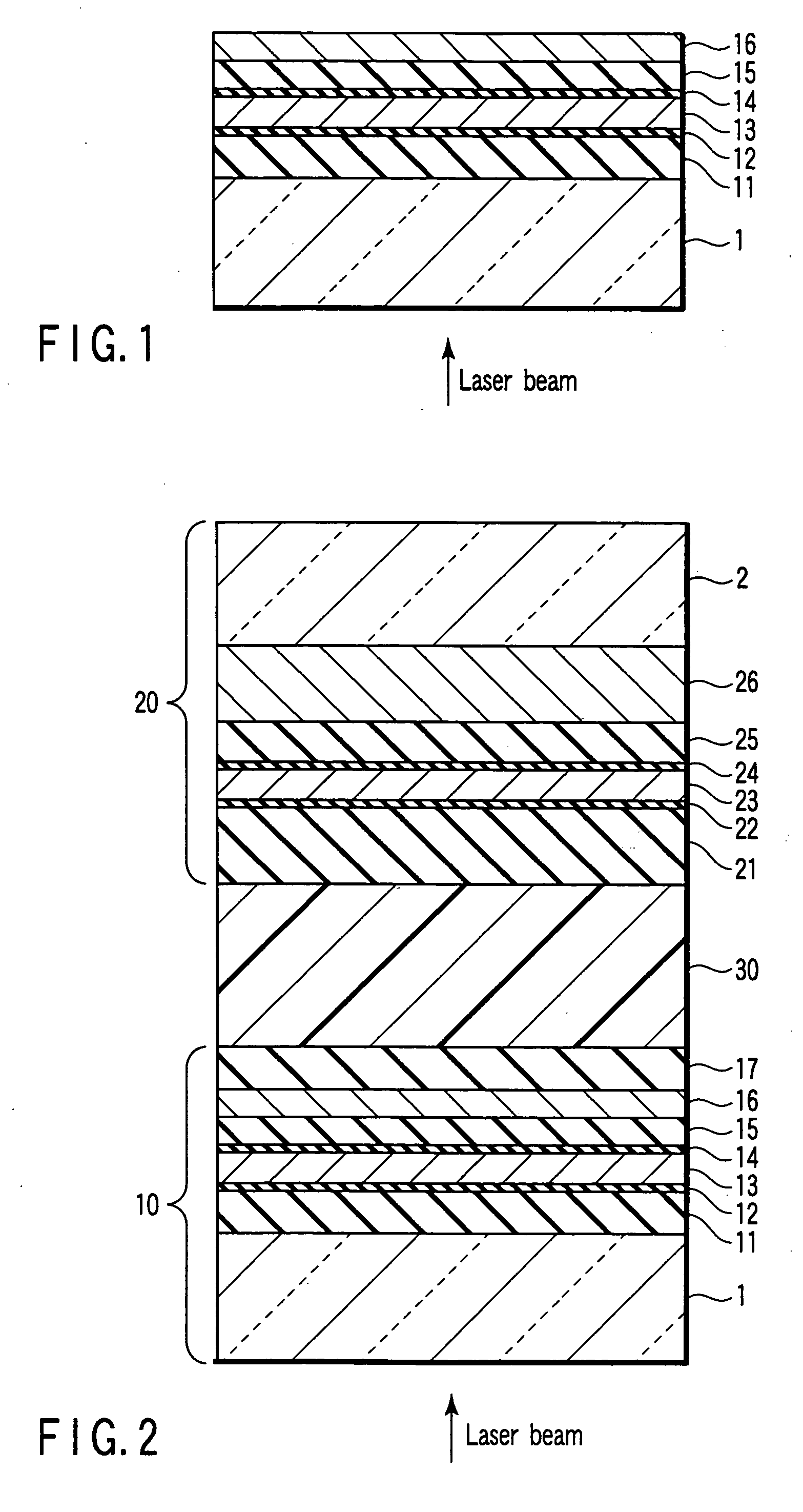
[0051] An L0 information layer was prepared by forming various films on the surface of a first substrate by sputtering, and an L1 information layer was prepared by forming various films on the surface of a second substrate by sputtering. The films are formed in different deposition chambers using the sputtering apparatus with multi process chambers.

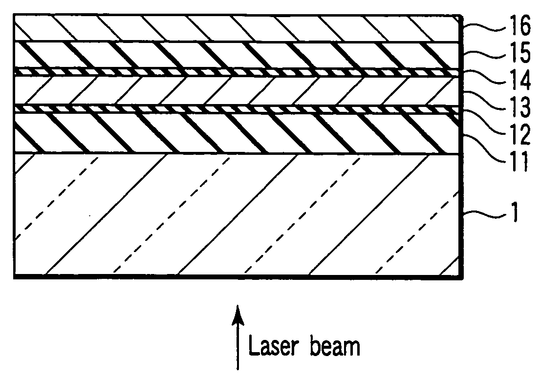
[0052] To be more specific, a ZnS:SiO2 film (first interference film), a lower interface film, a phase-change optical recording film, an upper interface film, a ZnS:SiO2 film (second interference film), an Ag alloy film (reflective film), and a ZnS:SiO2 film (thermal diffusion film) were formed successively on the surface of the first substrate in the order mentioned so as to prep...

examples 2 to 9

[0067] Discs of the construction equal to that of Example 1 were prepared by using various interface films. Specifically, interface films formed of HfSi0.4O4C0.5, HfSi0.1O2.5C0.1, HfSi0.2O3.5C0.01, HfSi0.15O2.8C0.001, HfSi0.18O3.1C0.0001, HfSi0.18O3C0.1, HfSi0.17O3.2C0.01, and HfSi1.6O2.9C0.0001 were used. Tests equal those applied in Example 1 were applied to the manufactured discs. The results of the tests are shown in Table 2.

[0068] As is apparent from Table 2, good characteristics were obtained in each of Examples 2 to 9.

TABLE 2AfterBeforeAfter OWenvironmentalExtinctionenvironmental testtesttestInterface filmcoefficientCNR[dB]SbERSbERSbERExample 1HfSi0.1O1.8C0.001054.62.0 × 10−52.4 × 10−52.9 × 10−5Example 2HfSi0.4O4C0.51.0 × 10−453.21.9 × 10−52.5 × 10−52.8 × 10−5Example 3HfSi0.1O2.5C0.11.1 × 10−553.82.4 × 10−52.8 × 10−52.9 × 10−5Example 4HfSi0.2O3.5C0.01053.62.2 × 10−52.6 × 10−52.8 × 10−5Example 5HfSi0.15O2.8C0.001052.12.4 × 10−52.9 × 10−52.9 × 10−5Example 6HfSi0.18O3.1C0.000...

examples 10 to 50

[0069] Discs of the construction equal to that in Example 1 were prepared by changing the material of the interface film. The materials used for the interface films were HfSiOCN, HfSiON, ZrSiOC, ZrSiOCN, TiSiOC, TiSiON, NbSiOC, NbSiOCN, AlSiOC, AlSiOCN, ZnSiOC, ZnSiOCN, YSiOC, YSiON, LaSiOC, LaSiOCN, CeSiOC, CeSiON, PrSiOC, PrSiON, SmSiOC, SmSiOCN, EuSiOC, EuSiON, GdSiOC, GdSiOCN, TbSiOC, TbSiOCN, DySiOC, DySiON, HoSiOC, HoSiOCN, ErSiOC, ErSiON, TmSiOC, TmSiOCN, YbSiOC, YbSiOCN, LuSiOC, and LuSiOCN. Incidentally, the composition of all the interface films was optimized so as to lower the extinction coefficient. Tests equal to those applied in Example 1 were applied to the discs thus manufactured. The results of the tests are shown in Tables 3 to 6. As is apparent from these tables, the disc prepared in any of these Examples was satisfactory in CNR and SbER.


PUM

PropertyMeasurementUnit
transmittanceaaaaaaaaaa
thicknessaaaaaaaaaa
wavelengthaaaaaaaaaa

Abstract

A phase-change optical recording medium has a recording film that brings about reversible phase-change between a crystalline phase and an amorphous phase upon irradiation with light and an interface film formed in contact with at least one surface of the recording film and comprising hafnium (Hf), silicon (Si), oxygen (O) and carbon (C).

Description

CROSS-REFERENCE TO RELATED APPLICATIONS [0001] This application is based upon and claims the benefit of priority from prior Japanese Patent Application No. 2003-369336, filed Oct. 29, 2003, the entire contents of which are incorporated herein by reference. BACKGROUND OF THE INVENTION [0002] 1. Field of the Invention [0003] The present invention relates to a phase-change optical recording medium in which a reversible phase-change between the crystalline and amorphous phases is brought about by light beam irradiation so as to record information. [0004] 2. Description of the Related Art [0005] (Principle of Phase-Change Optical Recording Medium) [0006] The phase-change optical recording medium, which uses a phase-change optical recording film that permits bringing about a reversible phase-change between the crystalline and amorphous phases upon irradiation with a light beam, operates according to the following principle. That is, recording is performed by heating the region irradiated ...

Claims


Application Information

Patent Timeline
Patent Type & Authority Applications(United States)
IPC IPC(8): B41M5/26G03G5/147G03G9/08G03G9/097G11B7/24G11B7/2403G11B7/243G11B7/2433G11B7/2437G11B7/254G11B7/257G11B7/2578
CPCG03G5/147Y10T428/21G03G5/14756G03G9/0821G03G9/097G11B7/2403G11B7/24038G11B7/252G11B7/2534G11B7/256G11B7/2578G11B7/259G11B2007/24306G11B2007/24308G11B2007/24312G11B2007/24314G11B2007/24316G11B2007/2432G11B2007/24328G11B2007/25706G11B2007/2571G11B2007/25711G11B2007/25713G11B2007/25715G03G5/14726
Inventor NAKAI, TSUKASAASHIDA, SUMIOYUSU, KEIICHIROTSUKAMOTO, TAKAYUKIOOMACHI, NORITAKENAKAMURA, NAOMASAICHIHARA, URARA
Owner KK TOSHIBA
Why Eureka
Try Eureka