
Soft magnetic alloy ribbon and its production method, and magnetic device having soft magnetic alloy ribbon

a soft magnetic alloy and production method technology, applied in the direction of magnetic materials, nanomagnetism, magnetic bodies, etc., can solve the problems of large core loss, high cost of co-based amorphous alloys, and inability to easily thin like amorphous ribbons, etc., to achieve excellent insulation, corrosion resistance and toughness, and high saturation magnetic flux density. , the effect of low core loss

Active Publication Date: 2011-11-10
HITACHI METALS LTD
View PDF4 Cites 40 Cited by
  • Summary
  • Abstract
  • Description
  • Claims
  • Application Information

AI Technical Summary

Benefits of technology

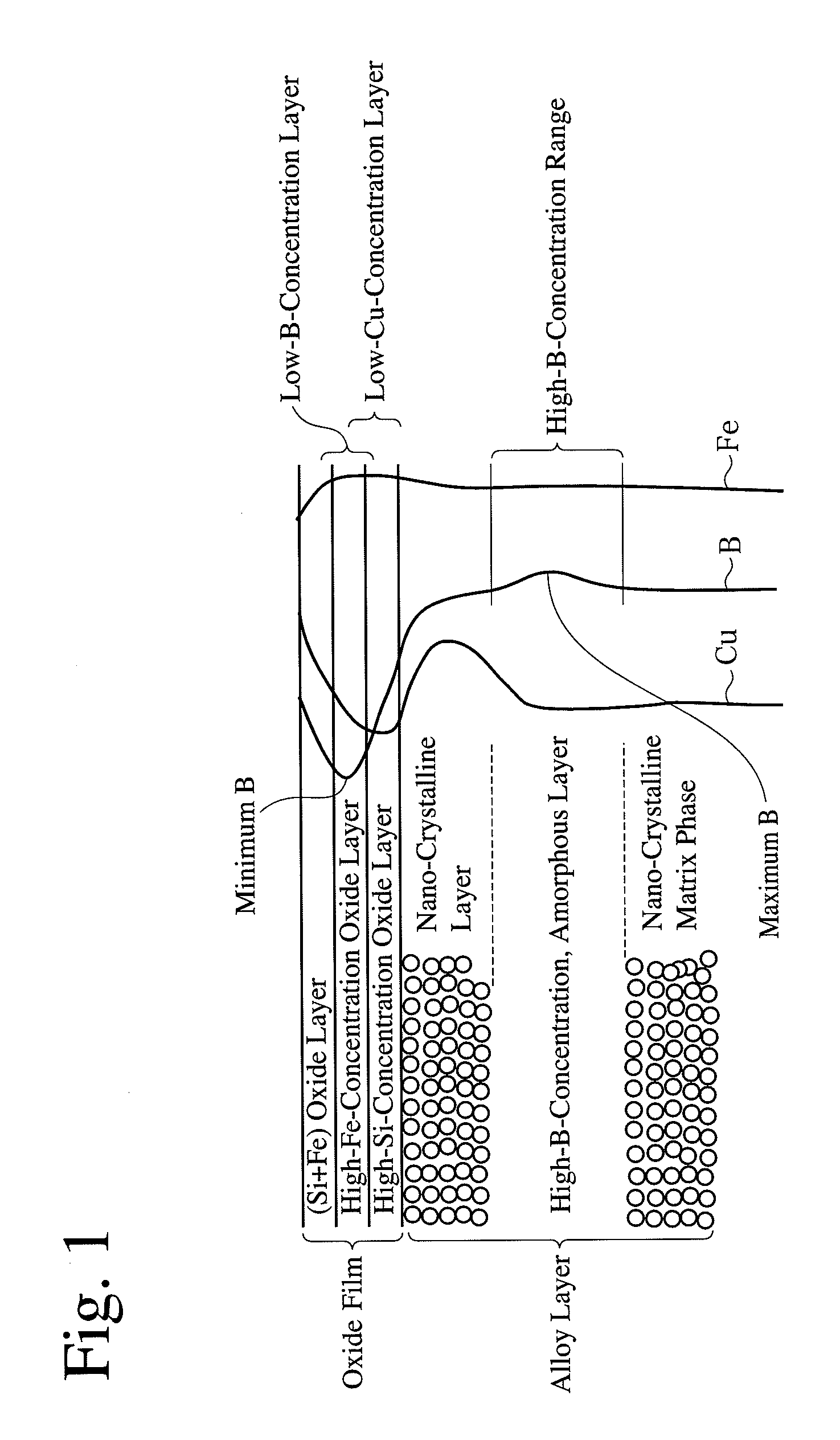
The present invention relates to soft magnetic alloy ribbons with high saturation magnetic flux density and low core loss as well as excellent insulation, corrosion resistance, and toughness. The invention is achieved by controlling the oxygen concentration in an atmosphere for annealing a primary fine-crystalline alloy ribbon having fine crystal nuclei. The soft magnetic alloy ribbons have a composition represented by Fe100-x-y-zAxByXz, wherein A is Cu and / or Au, X is at least one element selected from the group consisting of Si, S, C, P, Al, Ge, Ga, and Be, and z, y, and z are numbers (by atomic %) meeting the conditions of 0−22, 1−10, and x+y+z≦25, and have a matrix phase in which fine crystal grains having an average diameter of 60 nm or less are dispersed at a volume fraction of 50% or more in an amorphous phase. The soft magnetic alloy ribbons have excellent magnetic properties and can be used in magnetic devices. The method of producing the soft magnetic alloy ribbons involves ejecting an alloy melt onto a rotating cooling roll for quenching, stripping the resulting primary fine-crystalline alloy ribbon, and annealing it in an atmosphere containing a low concentration of oxygen or an oxygen concentration of 6-18%. The soft magnetic alloy ribbons have layers that are not divided by clear boundaries, but they have specific ranges in thickness.

Problems solved by technology

Silicon steel is inexpensive and has a high magnetic flux density, but it suffers large core loss in high-frequency applications, and it cannot be easily made thin unlike amorphous ribbons.
Co-based amorphous alloys are expensive and have as low saturation magnetic flux density as 1 T or less with practical compositions, providing large parts when used for high-power applications.
In addition, because of thermal instability, the Co-based amorphous alloys change with time, resulting in increased core loss.
However, the theoretical upper limit of a saturation magnetic flux density determined by the interatomic distance, the coordination number and the Fe concentration is as low as 1.65 T, and this Fe-based, amorphous alloy has large magnetostriction, characteristics deteriorated by stress, and a poor S / N ratio in an audible frequency band.
To improve the saturation magnetic flux density of the Fe-based, amorphous alloy, it was proposed to substitute part of Fe with Co, Ni, etc., but its effect is small despite high cost.
However, JP 2001-252749 A fails to describe the heat treatment atmosphere.
However, this soft magnetic alloy ribbon unsatisfactorily has a saturation magnetic flux density of about 1.6 T.
However, there is no Example conducting the heat treatment in the air.

Method used


Image

  • Soft magnetic alloy ribbon and its production method, and magnetic device having soft magnetic alloy ribbon
  • Soft magnetic alloy ribbon and its production method, and magnetic device having soft magnetic alloy ribbon
  • Soft magnetic alloy ribbon and its production method, and magnetic device having soft magnetic alloy ribbon

Examples


example 1

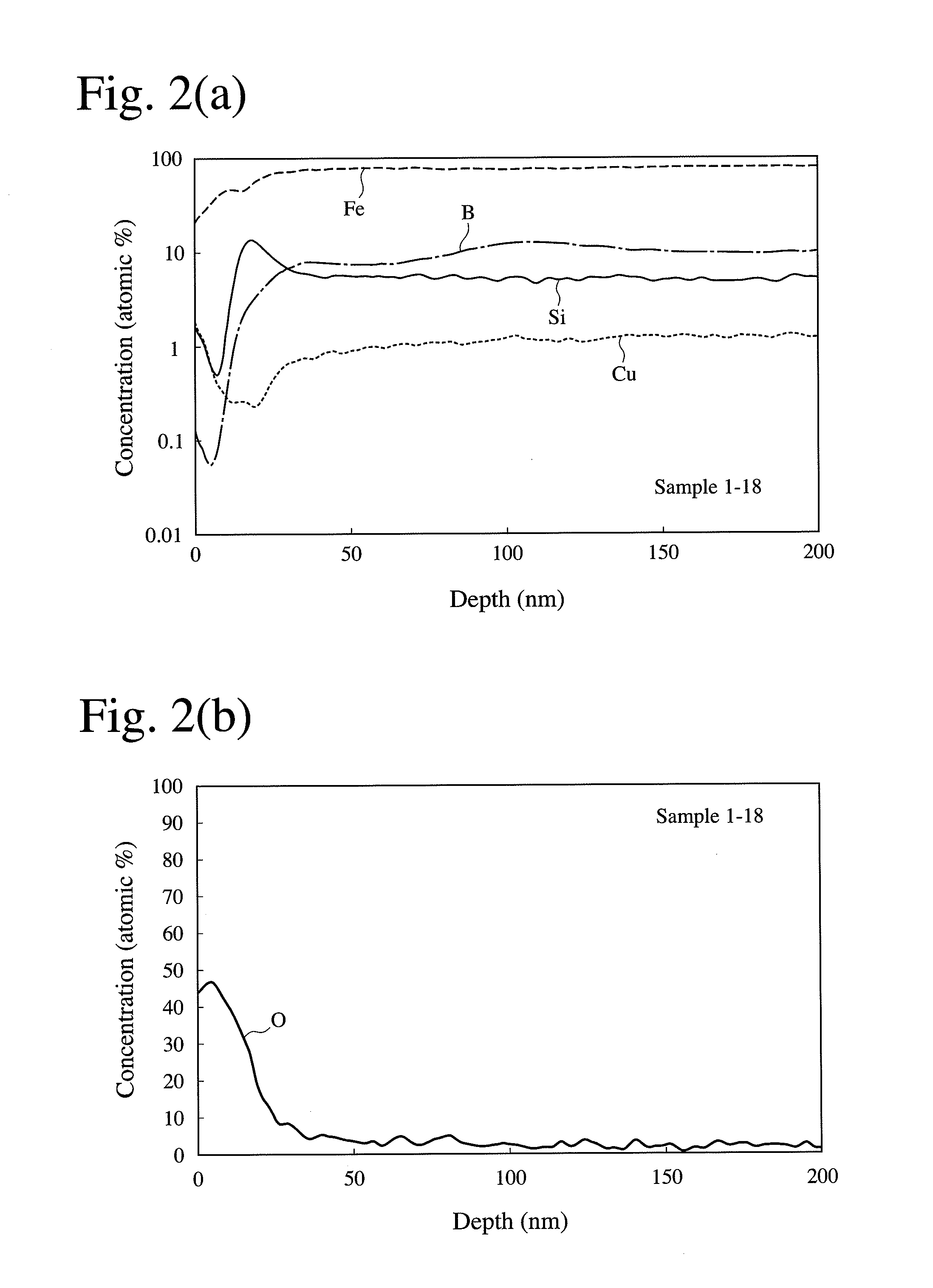
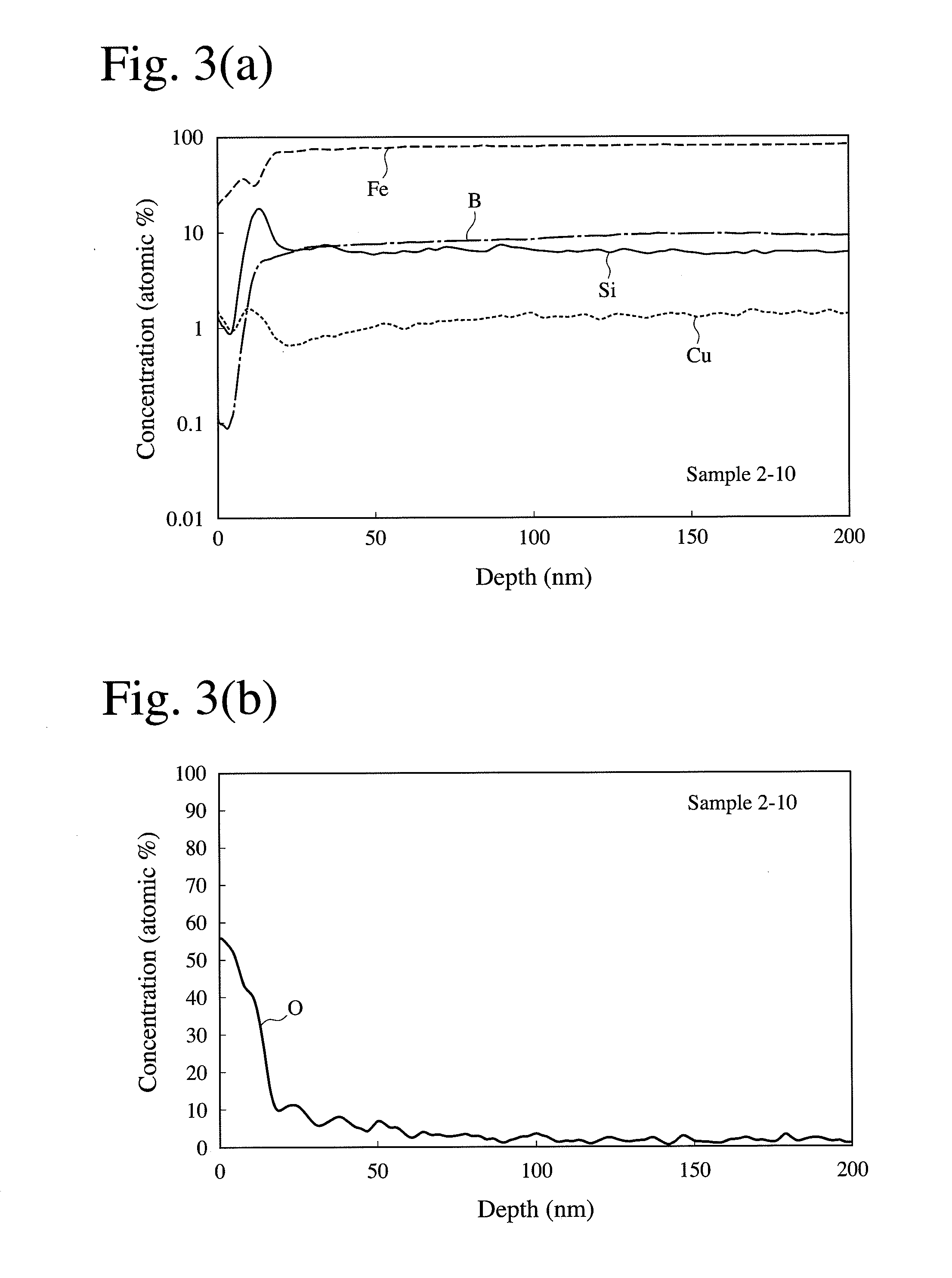
[0096]Alloy melts having the compositions shown in Table 1 were quenched by a single-roll method in the air to obtain primary fine-crystalline alloy ribbons of 5 mm in width and 16-25 μm in thickness each having a structure comprising fine crystal nuclei having an average diameter of 30 nm or less dispersed at a volume fraction of 2-25% in an amorphous phase, with varied stripping temperatures from the roll surface. The stripping temperature of each primary fine-crystalline alloy ribbon was measured by the method described below.

[0097]Each primary fine-crystalline alloy ribbon was placed in a furnace with a nitrogen atmosphere having an oxygen concentration of 10%, and subject to a nano-crystallization heat treatment under the conditions of heating at 120° C. / minute on average, and keeping the highest temperature of 450° C. for 5 minutes. The resultant soft magnetic alloy ribbon was measured with respect to the average diameter and volume fraction of fine crystal grains by the metho...

example 2

[0123]Soft magnetic alloy ribbons each having a structure, in which fine crystal grains having an average diameter of 60 nm or less were dispersed at a volume fraction of 50% or more in an amorphous phase, were produced from an alloy melt of Febal.Ni1Cu1Nb1Si4B12 (Sample 3-1), and an alloy melt having the same composition of Febal.Cu1Nb1Si4B12 except for containing no Ni (Sample 3-2), in the same manner as in Example 1 except for changing the stripping temperature to 300° C. The concentration distributions of Fe, Ni, B, Si, Cu, Nb and O from the free surface toward inside in each ribbon were measured by GDOES. The measurement results of Sample 3-1 are shown in FIG. 5, and the measurement results of Sample 3-2 are shown in FIG. 6. In FIGS. 5 and 6, the origin corresponds to the sample surface.

[0124]Sample 3-1 had a boundary between the oxide film and the nano-crystalline layer near 40 nm, and there was a high-B-concentration, amorphous layer having the highest B concentration near th...

example 3

[0125]Soft magnetic alloy ribbons each having a structure, in which fine crystal grains having an average diameter of 60 nm or less were dispersed in an amorphous phase at a volume fraction of 50% or more, were produced from alloy melts having the compositions shown in Table 5, in the same manner as in Example 1 except for changing the stripping temperature to 300° C. The depth at the highest B concentration was measured on each soft magnetic alloy ribbon. Also, core loss (P10 / lk) at 1 T and 1 kHz was measured on a wound core formed by each soft magnetic alloy ribbon. The results are shown in Table 5.

TABLE 5Depth (nm) atSam-Highest BCore Loss P10 / 1kpleCompositionConcentration(W / kg)4-1Febal.Ni1Cu1Nb1Si4B12554.14-2Febal.Mn1Cu1Nb1Si4B12354.04-3Febal.Co1Cu1Nb1Si4B12504.04-4Febal.V1Cu1Nb1Si4B12504.34-5Febal.Cr1Cu1Nb1Si4B12454.14-6Febal.Cu1Nb1Si4B12804.4

[0126]As is clear from Table 5, the high-B-concentration, amorphous layers were as deep as 30-100 nm. Also, these soft magnetic alloy rib...


PUM

PropertyMeasurementUnit
volume fractionaaaaaaaaaa
diameteraaaaaaaaaa
temperatureaaaaaaaaaa

Abstract

A method for producing a soft magnetic alloy ribbon having a composition represented by Fe100−x−y−zAxByXz, wherein A is Cu and / or Au, X is at least one element selected from the group consisting of Si, S, C, P, Al, Ge, Ga and Be, and x, y and z are numbers (by atomic %) meeting the conditions of 0<x≦5, 10≦y≦22, 1≦z≦10, and x+y+z≦25, and comprising a matrix phase in which fine crystal grains having an average diameter of 60 nm or less are dispersed at a volume fraction of 50% or more, part of an oxide film formed on the surface being a layer having a lower B concentration than the average B concentration of the matrix phase; comprising the steps of (1) ejecting an alloy melt having the above composition onto a rotating cooling roll for quenching, to form a primary fine-crystalline alloy ribbon having a matrix phase, in which fine crystal nuclei having an average diameter of 30 nm or less are dispersed at a volume fraction of more than 0% and less than 30% in an amorphous phase; and then (2) annealing the primary fine-crystalline alloy ribbon in an atmosphere having an oxygen concentration of 6-18%.

Description

FIELD OF THE INVENTION[0001]The present invention relates to a soft magnetic alloy ribbon having a high saturation magnetic flux density and low core loss, as well as excellent insulation, corrosion resistance and toughness, and its production method, and a magnetic device comprising such soft magnetic alloy ribbon.BACKGROUND OF THE INVENTION[0002]Soft magnetic materials used for various transformers, reactors, choke coils, noise reduction parts, laser power sources, magnetic pulse power devices for accelerators, motors, power generators, etc. include silicon steel, ferrite, amorphous alloys, Fe-based, nano-crystalline alloys, etc. Silicon steel is inexpensive and has a high magnetic flux density, but it suffers large core loss in high-frequency applications, and it cannot be easily made thin unlike amorphous ribbons. Because of a low saturation magnetic flux density, ferrite is easily saturated magnetically in high-power applications with large operation magnetic flux densities. Co...

Claims


Application Information

Patent Timeline
Patent Type & Authority Applications(United States)
IPC IPC(8): C21D6/00C21D1/00H01F1/01
CPCB82Y25/00B82Y30/00C21D1/74C21D1/76C21D8/1211C21D8/1244H01F1/15333C22C38/02C22C38/16C22C38/32H01F1/153H01F1/15391C21D2201/03
Inventor OHTA, MOTOKIYOSHIZAWA, YOSHIHITO
Owner HITACHI METALS LTD
Learn More