[0013] In accordance with one aspect of the invention,
cleanability and color change times are substantially improved by a supply concept in which the functions of a hopper or container are combined with ductwork of a
material recovery system. In one embodiment, a supply is provided having a container that is connectable to an after
filter system that typically draws large volumes of air from a spray booth and an overspray
recovery unit such as a
cyclone. In a particular embodiment, the supply is in the form of a duct that is connectable to a recovery system. By having a supply that is connectable as a duct to the recovery system, cleaning is greatly simplified and faster. Preferably although not necessarily the hopper function includes fluidizing the material therein.
[0014] In accordance with another aspect of the invention,
cleanability and color change times are substantially improved by a supply concept in which the functions of a hopper or container are combined with ductwork for a
material recovery system so that negative pressure can be used during a cleaning and color change operation. In one embodiment, a hopper or supply is provided in the form of a duct that is selectively connectable to a source of negative pressure, such as for example, a
material recovery system. The duct connection is arranged such that during a material application process the supply is substantially disconnected from the negative pressure source so that the supply operates generally at
ambient air pressure.
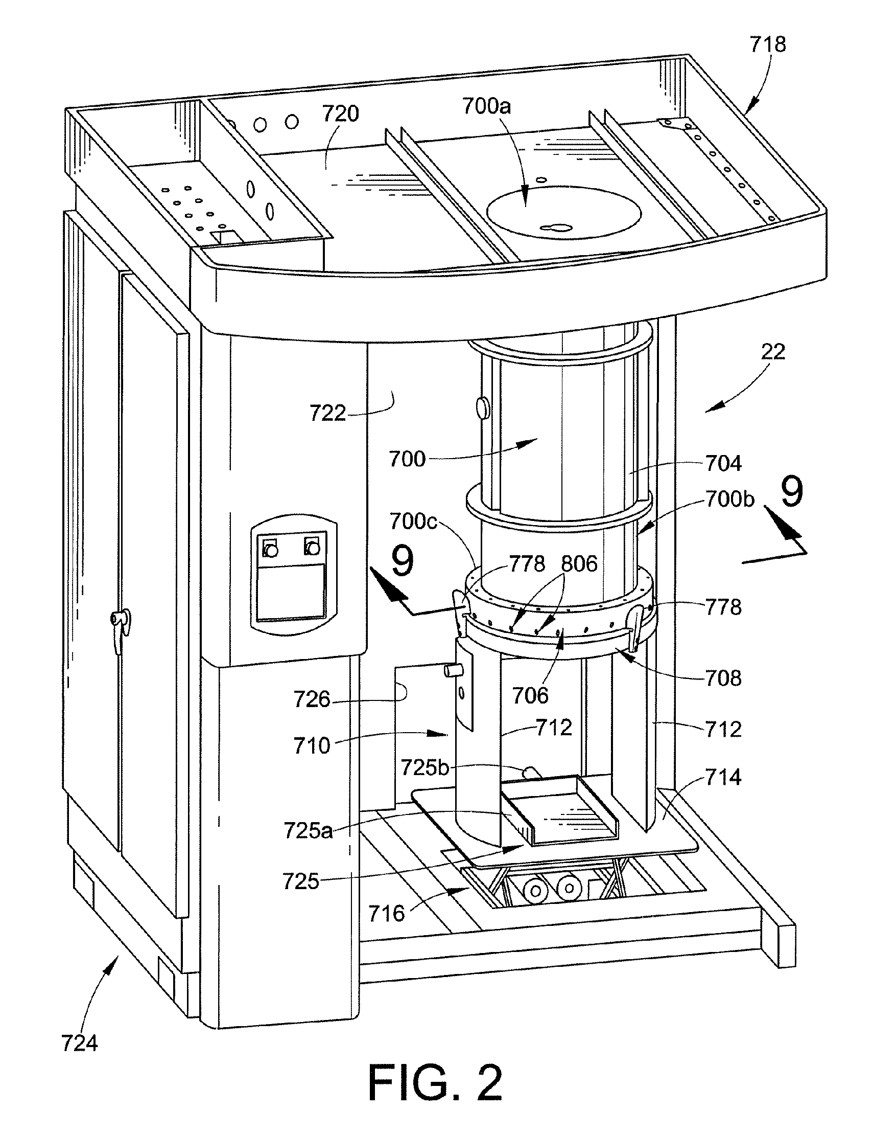
[0015] In accordance with another aspect of the invention, a supply is contemplated that combines the functions of a hopper, suction tubes and optionally a fluidizing arrangement. In one embodiment, the hopper is in the form of a duct with a
siphon ring and fluidizing plate at one end so that fluidized powder is extracted from the duct through one or more radial outlets in the
siphon ring. Other embodiments include arranging the duct in selectable fluid communication with a recovery system. This greatly simplifies cleaning and color change by allowing the recovery system to remove most of the powder residue from the fluidizing hopper and siphon ring. In accordance with a further aspect of the invention, the siphon ring may be used as a source to a dense phase pump.
[0016] In accordance with another aspect of the invention, a fluidizing arrangement is contemplated that improves the mixing and
fluidization of powder by providing a convective-like circulatory flow within a duct. In one embodiment, the fluidizing arrangement includes a fluidizing
bed that is of larger
diameter than the associated duct. This embodiment produces an increased vertical flow velocity near the outer portions of the fluidizing plate, in effect causing a circulating motion to the material, thereby improving mixing and re-mixing of material therein. In a more specific embodiment, a transition duct or ring that has an
involute profile enhances the circulatory motion while providing a surface area that is easy to clean.
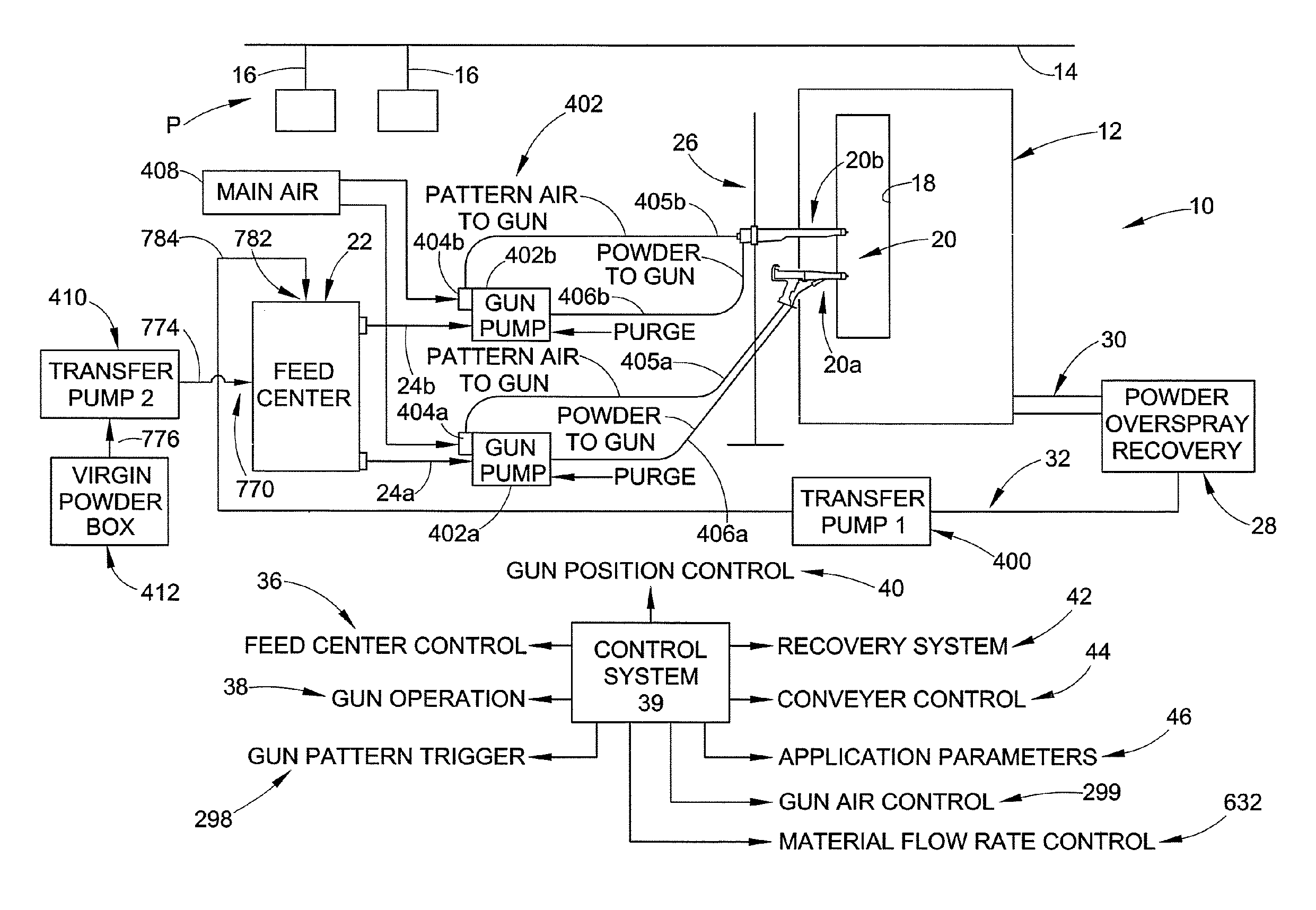
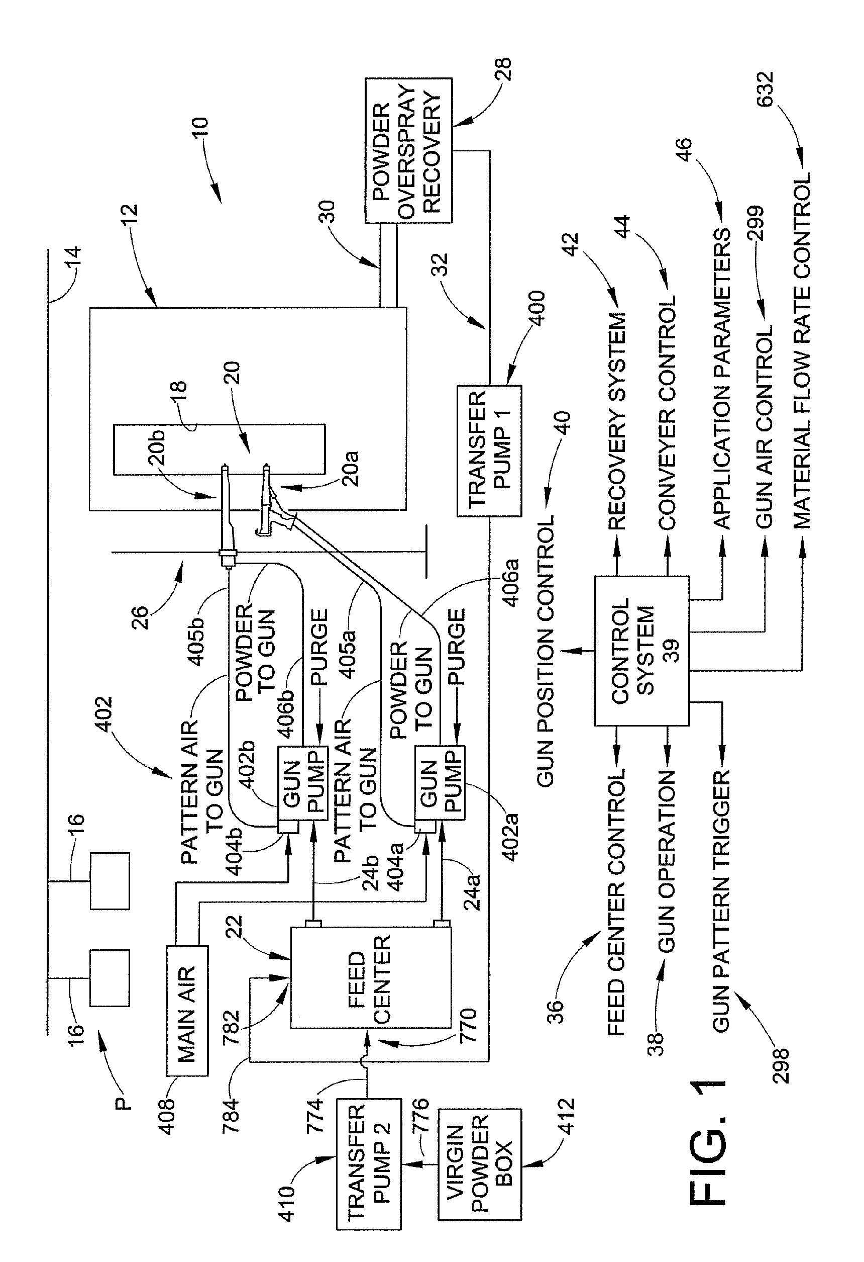
[0017] In accordance with another aspect of the invention, a supply is provided for a material application system which combines the functions of a hopper, suction tubes and fluidizing arrangement with duct work of a material recovery system. Such an arrangement allows for faster and simpler purging of the flow paths between the supply and the pumps, as well as faster and simpler cleaning of the hopper, fluidizing arrangement and powder extraction devices. In one embodiment, a hopper is realized in the form of a duct that is connectable to a recovery system, and also includes a fluidizing member and siphon ring. The siphon ring allows for pumps to access the fluidized material inside the duct.
[0021] In accordance with another aspect of the invention, a
sieve arrangement is provided that is easy to access and clean and has improved sieving action. This is achieved by a sieve design in which the sieve is manually accessible through an opening in a duct and is optionally provided with an integral vibration mechanism. In one embodiment, a sieve is provided inside a hopper in the form of a duct with the sieve being manually positioned for cleaning and sieving operations. In one embodiment, an
inflatable seal is used to secure the sieve in its sieving position in a fluid tight manner but that can also be deflated for easy movement of the sieve to a cleaning position. In accordance with another aspect of the invention, the cleaning position of a sieve is located in or near the duct-like hopper so that during cleaning the residue powder is drawn up into a recovery system. In accordance with another aspect of the invention, a moveable sieve can be positioned within a duct-like hopper that is connectable to ductwork of a recovery system. The recovery system removes much of the powder residue on the sieve during a color change or cleaning operation. In still a further embodiment the sieve is provided with an integral vibration device.

