Micro-heating apparatus for locally controlling the temperature in a mold

a mold temperature and micro-heating technology, which is applied in the direction of electrical equipment, ohmic resistance heating, electric heating, etc., can solve the problems of affecting the quality of molds, so as to achieve high flow length/sidewall thickness, high heating effect, and high transfer ratio

Inactive Publication Date: 2005-06-02
U TECH MEDIA
View PDF9 Cites 16 Cited by
  • Summary
  • Abstract
  • Description
  • Claims
  • Application Information

AI Technical Summary

Benefits of technology

[0010] It is an advantage of the claimed invention that the micro-heater and the temperature detector of the micro-heating apparatus fabricated by MEMS process are installed near the insert-mold so that the micro-heater can directly contact the plastic material. Therefore it is easy to get a high heating effect and the temperature of the plastic material can be directly controlled. Since the micro-heater can locally heat the plastic material and control the temperature, the plastic material can flow well on the insert-mold with microstructures during the filling and compressing process. Even when the microstructures have a high aspect ratio and a high flow length / sidewall thickness (L / T) ratio, the transfer ratio is still very high.
[0011] It is a second advantage of the claimed invention that the micro-heater is set near the insert-mold, so as to contact the plastic material directly. As a result, for some specific microstructures having high aspect ratios or high thickness variation of the geometric figure, the micro-heating apparatus can locally control the mold temperature to observe a better flow of the plastic material without raising the temperature of the whole mold.
[0012] It is a third advantage of the claimed invention that the micro-heater can heat the plastic material again and again so that it has a function of locally annealing the plastic material. In addition, the temperature detector can adjust the plastic material to an appropriate temperature. Accordingly, during the filling and compressing processes, the plastic material does not generate residual stress under pressure.
[0013] It is a fourth advantage of the claimed invention that a specific temperature gradient can be performed by using the micro-heater and the temperature detector during the cooling process. Therefore, the deformed situations of the plastic material caused by various temperature differences can be prevented.
[0014] It is a fifth advantage that the claimed invention fabricates the micro-heater and the temperature detector arranging in matrix by MEMS processes on the injection mold. Therefore the claimed invention can produce wafer-level plastic chips by an injection molding process, i.e. the plastic wafer technology. And the produced wafer-level plastic chips can be packaged together with a substrate having integration circuits and MEMS elements thereon so as to reduce the cost of production and raise the profit of mass production.

Problems solved by technology

As a result, controlling the mold temperature is still a big issue in manufacturing.
However, the mass of the hot oil is larger, so that it takes several minutes to complete the heating process.
Consequently, it will decrease profit and effect of the fabrication.
Although the prior-art external power device can raise the mold temperature faster, the heat from the power device diffuses in all directions to the whole mold, and therefore the system will lose heat before the heat reaches the surface of the plastic material.
Furthermore, since there is a certain heat transfer distance between the external power device and the surface of the plastic material, it is difficult to accurately control the temperature of the surface of the plastic material.
As a result, the heating effect is not good enough when the prior-art external power device is employed.
Thus it still cannot match the requirement of locally heating the mold and controlling the temperature.
“Nanoreplication in polymers using hot embossing and injection molding” by H. Schift et al. points out that it will decrease the transfer ratio or cause the plastic material to incompletely fill the mold if the mold temperature is not high enough when the plastic material flows through the microstructures, with a high aspect ratio, of the stamper.
However, in contrast to the injection-molding method, the hot embossing method has the following disadvantages: (a) failing to completely transfer microstructures having a high aspect ratio; (b) failing to generate an uniform product; (c) having limitations to some geometric figures of microstructures; (d) easily occurrence of inner stress; (e) needing a vacuum system when requiring high quality.

Method used


Image

  • Micro-heating apparatus for locally controlling the temperature in a mold
  • Micro-heating apparatus for locally controlling the temperature in a mold
  • Micro-heating apparatus for locally controlling the temperature in a mold

Examples


Embodiment Construction

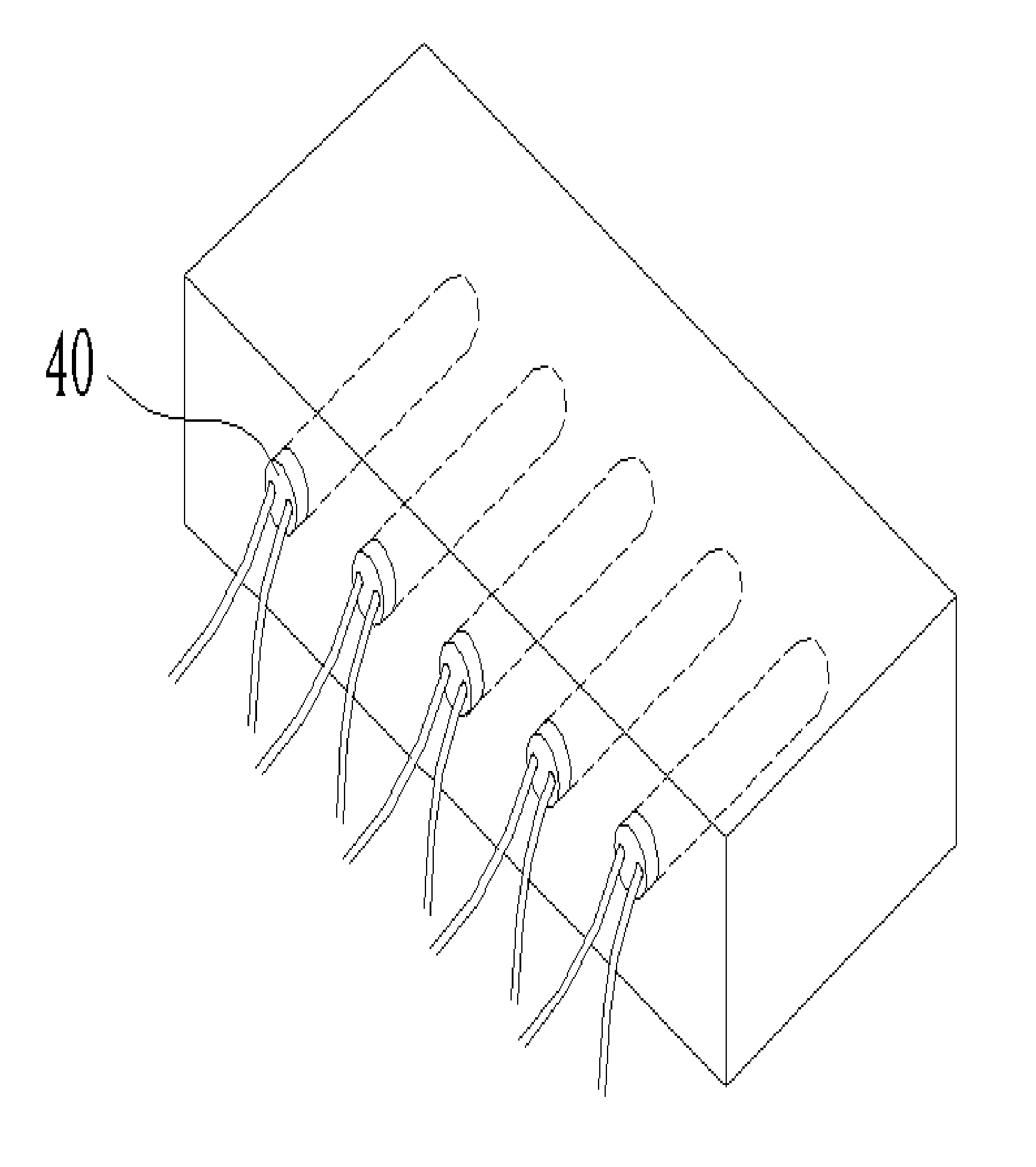
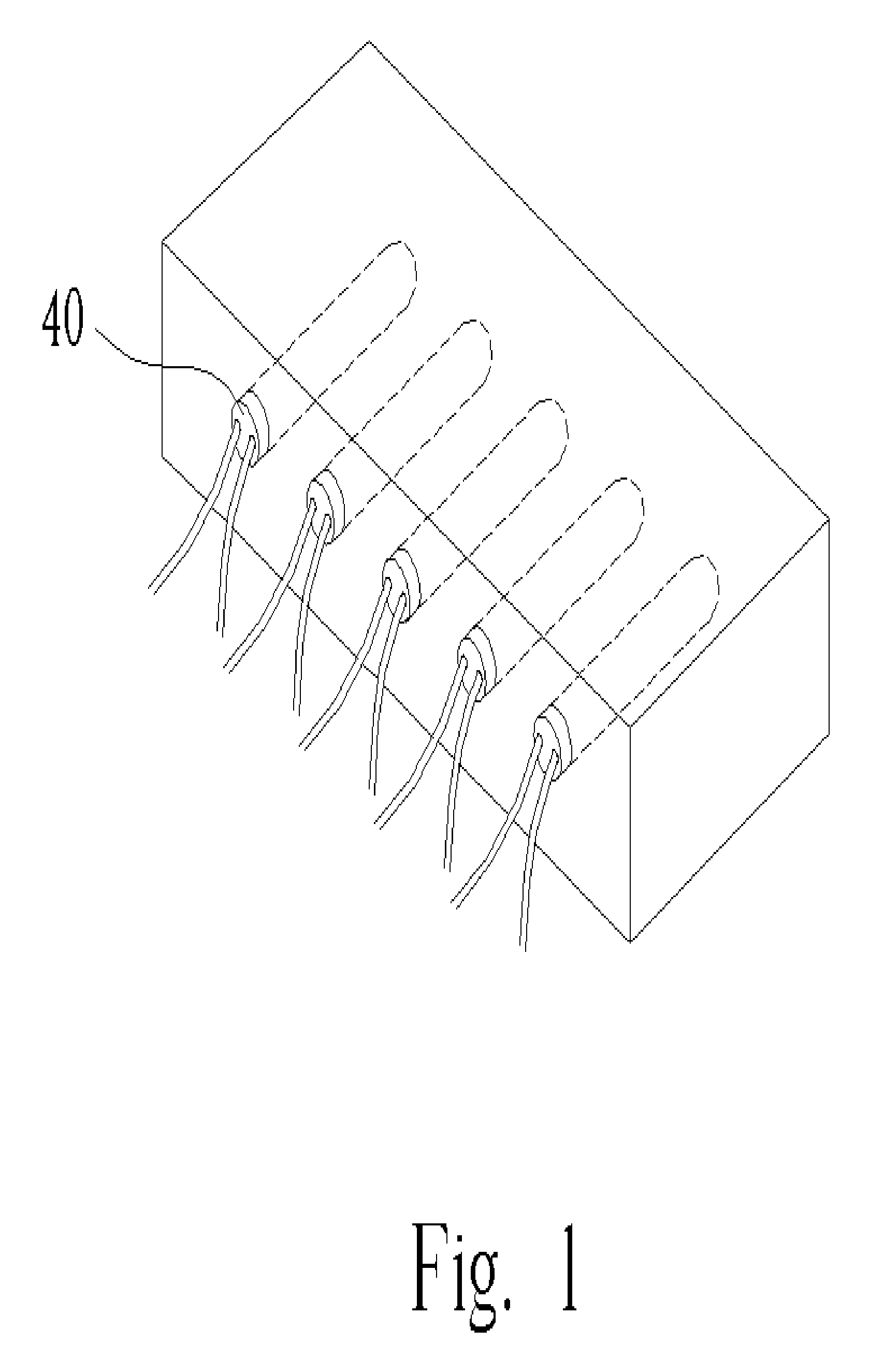
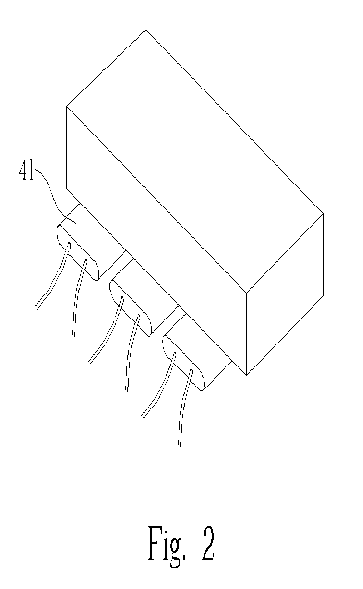
[0029] The present invention comprises at least a micro-heater fabricated by MEMS set in an injection and hot embossing mold for supplying heat resource in a local portion of the mold when molding a product. The present invention further comprises at least a resistance temperature detector (R.T.D) near the micro-heater so that the micro-heater can locally control the mold temperature to an accuracy of ±5° C. Since the arrangement of the micro-heaters insures that the micro-heaters can locally heat the mold around the microstructures, the plastic material can flow in a better station in the mold having fine figures or high thickness variation during filling and compressing processes.

[0030] Please refer to FIG. 4. FIG. 4 is a schematic diagram of the plastic material 15 flowing through a portion of a stamper 17 according to the present invention. During the injection molding process, the plastic material 15 flows through the portion, with high thickness variation, of the stamper 17. ...


PUM

PropertyMeasurementUnit
mold temperatureaaaaaaaaaa
sizeaaaaaaaaaa
resistanceaaaaaaaaaa

Abstract

A micro-heating apparatus for locally controlling a temperature in a mold includes substrate, at least a micro-heating module installed on the substrate, and at least a temperature detector installed on the substrate near the micro-heater for measuring the local temperature. The micro-heating module includes a micro-heater, an external power circuit, and a connection electrode for connecting the external power circuit and a programmable external power device. The substrate with the micro-heating module and the temperature detector thereon is capable of combining with the mold so that the micro-heater contacts a plastic material in the mold. The programmable external power device is used for connecting to the external power circuit to control the micro-heater to heat the plastic material so as to control the temperature when the temperature around an interface of the plastic material and the micro-heater is measured.

Description

BACKGROUND OF INVENTION [0001] 1. Field of the Invention [0002] The invention relates to a micro-heating apparatus, and more particularly, to a micro-heating apparatus for locally controlling a temperature in a mold. [0003] 2. Description of the Prior Art [0004] According to the development of the IC fabrication in recent years, semiconductor technology has come to maturity. Therefore semiconductor products have been pushed for size reductions to match the trend of market requirements. The micro-electro-mechanical system (MEMS) technology based on the semiconductor process also has a huge amount of applications. For example, the elements with microstructures, such as the micro-sensor, micro-actuator, and micro-switch, and the systems on a chip (SOC) or the lab on a chip (LOC) are common applications of MEMS. Micro-heaters fabricated by MEMS are widely applied in many documents. The micro-heaters are commonly used in air detectors, chemical detectors, and polymerase chain reaction (P...

Claims


Application Information

Patent Timeline
Patent Type & Authority Applications(United States)
IPC IPC(8): B29C43/52B29C45/26B29C45/56B29C45/73B29C45/78H05B1/02
CPCB29C33/08B29C43/52B29C45/263B29C2043/025B29C45/73B29C45/78B29C45/561
Inventor HUANG, JUNG-TANG
Owner U TECH MEDIA
Why Eureka
Try Eureka