Illumination optical system and image-taking apparatus

an optical system and image-taking apparatus technology, applied in lighting and heating apparatus, instruments, condensers, etc., can solve the problems of inability to achieve further miniaturization of the illumination optical system, inability to maintain the shape, optical characteristics, and inability to improve the optical characteristics, mechanical characteristics and the like of the optical member. the effect of improving the characteristics of the material

Inactive Publication Date: 2005-06-02
CANON KK
View PDF6 Cites 11 Cited by
  • Summary
  • Abstract
  • Description
  • Claims
  • Application Information

AI Technical Summary

Benefits of technology

[0016] It is an object of the present invention to provide an illumination optical system which can achieve further miniaturization by improving the characteristics of the material of the optical member, in addition to the shape of the optical member.

Problems solved by technology

However, even with the use of the above-described technique, it is difficult to achieve further miniaturization of the illumination optical system, while maintaining their existing optical characteristics.
This presents the possibility that some optical materials may be deformed or discolored by heat generated by the light source and thus may be unable to maintain the shape, optical characteristics and the like of the optical member.
However, this is basically aimed at uniformly diffusing light, and cannot simultaneously improve the optical characteristics, mechanical characteristics and the like of the optical member.
H11 (1999)-188268 is extremely expensive as it uses glass as the base material, and a refractive index gradient is provided for the glass tube, which serves as the light source.

Method used


Image

  • Illumination optical system and image-taking apparatus
  • Illumination optical system and image-taking apparatus
  • Illumination optical system and image-taking apparatus

Examples


embodiment 1

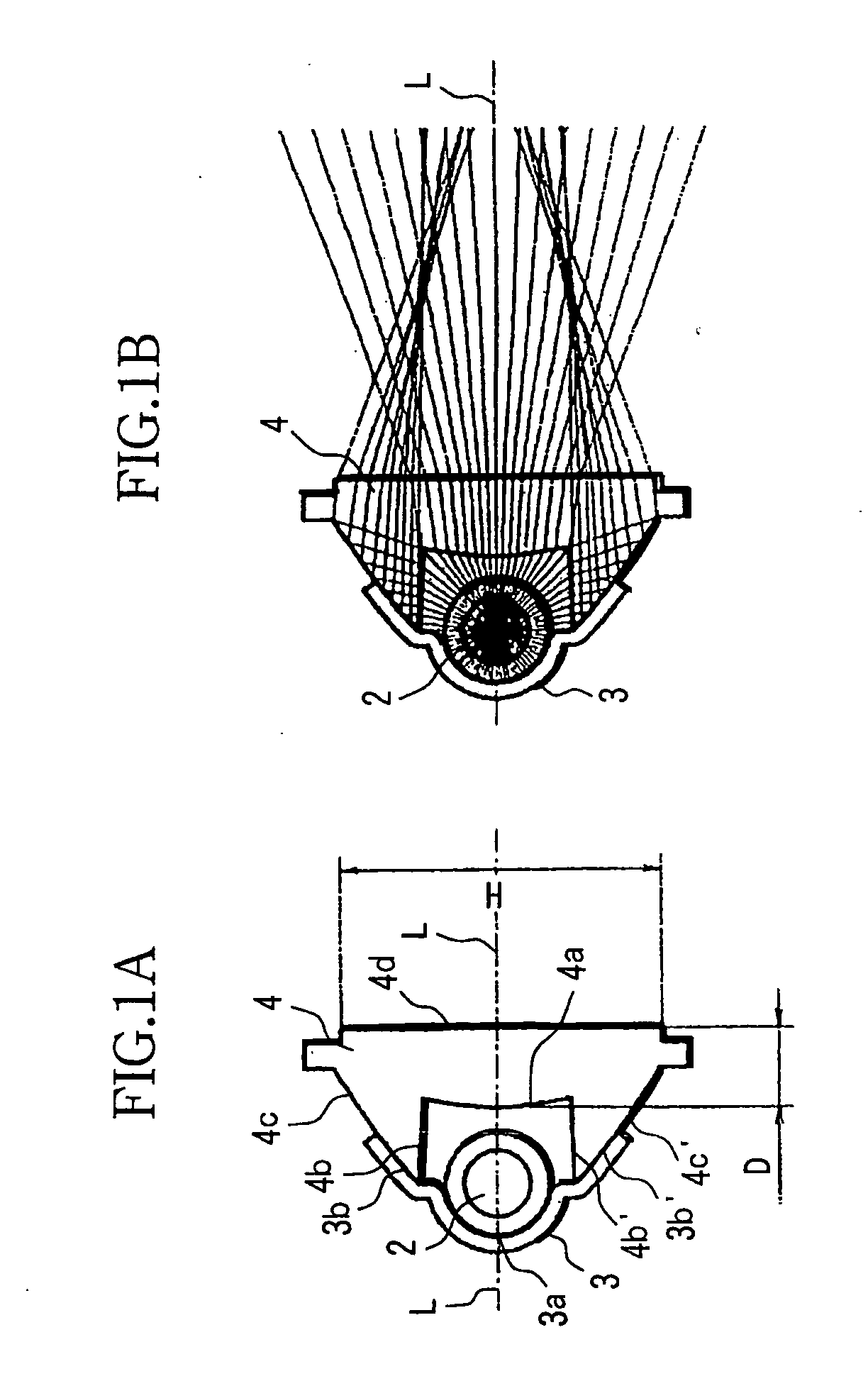
[0035]FIGS. 1, 3 and 5 show the structure of an illumination optical system according to Embodiment 1 of the present invention, in particular, an illumination optical system incorporated in a camera (image-taking apparatus). FIGS. 1A and B show cross-sectional views (vertical cross-sectional views) in a direction orthogonal to the optical axis of the illumination optical system, and FIG. 3 shows a horizontal cross-sectional view of the illumination optical system. FIGS. 1B and 3 also show traced drawings of light beams for representative light beams emitted from the center of the light source. FIG. 5 shows an exploded perspective view of the illumination optical system. FIG. 6 shows a camera equipped with the illumination optical system.

[0036] Referring first to FIG. 6, reference numeral 11 denotes a camera body, and 12 denotes an image-taking lens barrel disposed approximately at the center on the front of the camera body 11. Reference numeral 1 denotes an illumination unit which ...

embodiment 2

[0090]FIGS. 7A and B show an illumination optical system according to Embodiment 2 of the present invention. Similarly to Embodiment 1, this illumination optical system is used for illumination units incorporated in cameras. It should be noted that this embodiment is an example of a partial modification of Embodiment 1, and the figures show only the vertical cross-sectional views corresponding to those shown in FIG. 1 of Embodiment 1. Since the basic structure is substantially the same as that of Embodiment 1, the overlapping components are only briefly described. In addition, FIGS. 7A and B show the shapes at the same cross section, and FIG. 7B is a diagram in which a traced drawing of light beams for representative light beams emitted from the light source center has been added to FIG. 7A.

[0091] In FIGS. 7A and B, reference numeral 22 denotes a light-emitting discharge tube (xenon tube), and 23 denotes a reflector. The reflector 23 is formed in substantially the same shape as the...

embodiment 3

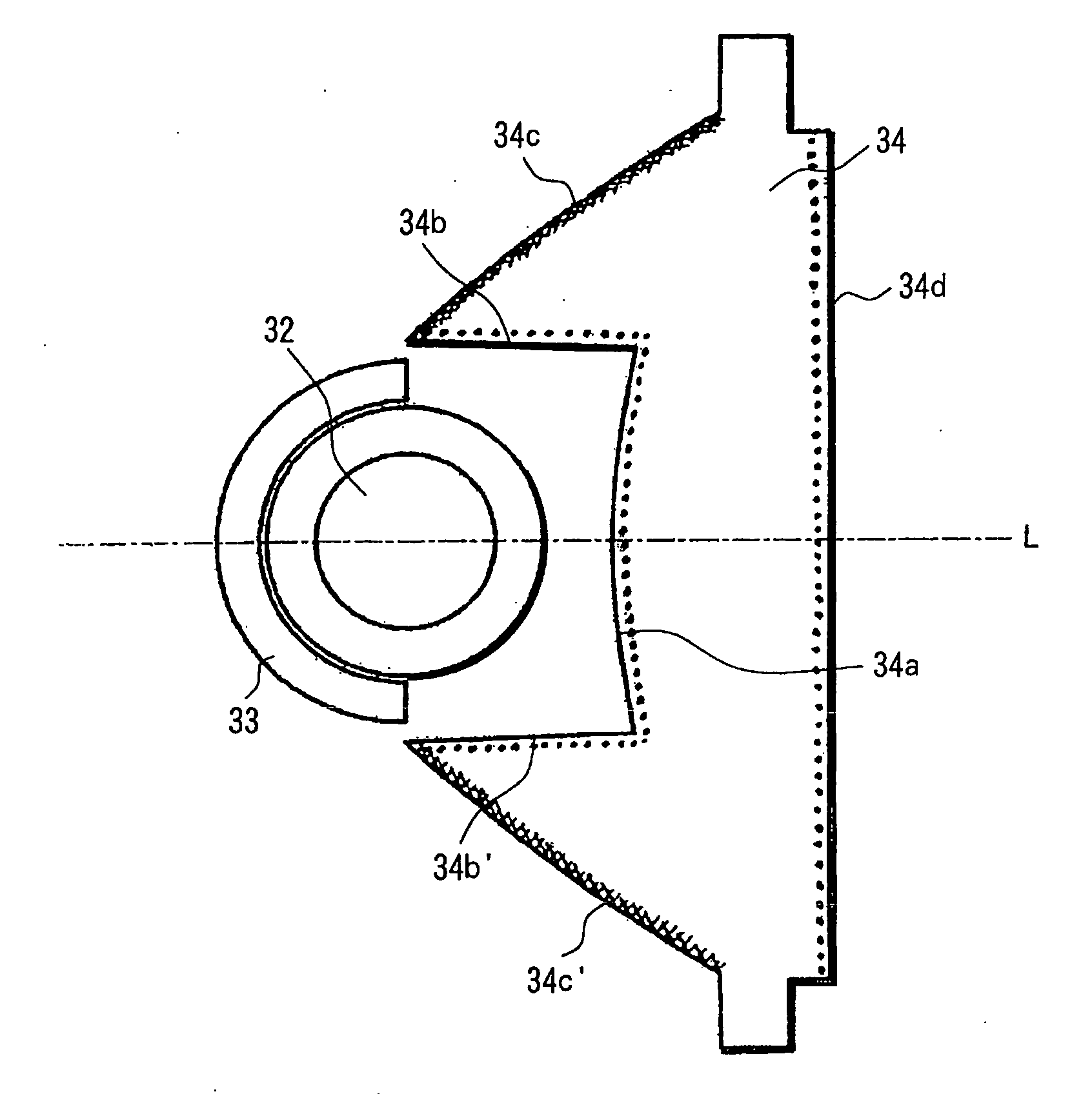
[0109]FIG. 8 shows an illumination optical system according to Embodiment 3 of the present invention. Similarly to Embodiment 1, this illumination optical system is used for illumination units incorporated in cameras. This embodiment is substantially equivalent to Embodiment 1 in terms of the shape, but the concentration distribution of ultrafine inorganic particles of a nanocomposite used as the material of the optical member is partially biased in order to take the full advantage of the characteristics of the nanocomposite. That is, whereas various optical and mechanical characteristics of the optical material of the optical members 2 and 24 described in Embodiments 1 and 2 are improved by uniformly dispersing the ultrafine inorganic particles in the base material, the optical characteristics of this embodiment are further improved by locally varying the concentration distribution within the optical member, more specifically, by varying the concentration in the vicinity of the sur...


PUM

PropertyMeasurementUnit
particle sizeaaaaaaaaaa
refractive indexaaaaaaaaaa

Abstract

An illumination optical system is disclosed, which can achieve miniaturization by improving the characteristics of the material of the optical member. The illumination optical system according to the present invention includes a light source and an optical member disposed in a direction of irradiation of light from the light source. The optical member is made of a particle-containing material with particles having a particle size smaller than 1 μm contained in a base material made of a resin material.

Description

BACKGROUND OF THE INVENTION [0001] 1. Field of the Invention [0002] The present invention relates to illumination optical systems, in particular to illumination optical systems used as illumination units or the like for image-taking apparatuses. [0003] 2. Description of Related Art [0004] Conventionally, illumination optical systems condense a luminous flux emitted from a light source within the necessary irradiation angle range with high efficiency, using an optical member such as a Fresnel lens or a reflector. The shape of the above-described optical member is optimized, and the shape of each portion of the illumination optical system is defined so as to provide predetermined light distribution characteristics. [0005] On the other hand, as digital cameras, portable devices and the like equipped with such illumination optical systems have been increasingly downsized in recent years, miniaturization of the illumination optical systems has also been advanced. Then, there have been va...

Claims


Application Information

Patent Timeline
Patent Type & Authority Applications(United States)
IPC IPC(8): G03B15/02C08K3/22C08K3/36C08L33/12F21V5/02F21V7/22F21V8/00G02B3/00G02B5/02G02B5/20G02B6/10G02B19/00G02B27/00G03B15/05
CPCG02B3/0087G02B5/206G02B6/0008G02B19/0028G02B6/0041G02B19/0047G02B6/0033
Inventor TENMYO, YOSHIHARU
Owner CANON KK
Why Eureka
Try Eureka