Plasma enhanced bonding for improving adhesion and corrosion resistance of deposited films

a technology of enhanced bonding and deposited films, which is applied in the field of chemical vapor deposition systems, can solve the problems of severe wear and erosion environment, major corrosion of industrial piping and other components such as valves and pumps, and the oil industry, in particular, faces severe corrosive environments, etc., and achieves the effect of reducing the probability of chemical undercutting, and improving the chemical resistance of dlc coatings

Active Publication Date: 2009-01-15
AGM CONTAINER CONTROLS
View PDF6 Cites 10 Cited by
  • Summary
  • Abstract
  • Description
  • Claims
  • Application Information

AI Technical Summary

Benefits of technology

[0016]In addition to being used as an under layer, Ge and GeC are well suited for use as a cap layer for a DLC coating. As an under layer, Ge and GeC reduce the likelihood of chemical undercut on rough metal substrates, where the under layer may also contain silicon, particularly when the silicon is deposited from silane or tetramethylsilane. Using Ge, GeC, or Ge-doped DLC as the top layer prevents chemical penetration from above. Using Ge or GeC blended with hydrocarbon improves chemical resistance of DLC coatings. Additionally, Ge or GeC reduces the porosity of a DLC coating. Ge or GeC reduces stress of the DLC coating and may be used to increase the thickness of the DLC coating. Precursors containing Ge and GeC improve the composition and material property uniformity along the length of the workpiece, such as a pipe.

Problems solved by technology

The corrosion of industrial piping and other components such as valves and pumps is a major problem in some industries.
The oil industry, in particular, faces severely corrosive environments, with corrosive gases and liquids such as H2S (hydrogen sulfide) at elevated temperatures and pressures.
Additionally, these conditions form severe wear and erosion environments.
Plasma enhanced CVD (PECVD) enables depositing films at reduced temperatures, but the energy delivered by plasma typically is not sufficient to provide the desired level of adhesion.
The method description is limited to low k layers on semiconductor substrates and not described for DLC coatings on steel substrates, also ion implantation techniques cannot be applied to internal surfaces as they are limited to line-of-sight very low pressure processes.
This technique, while an improvement over prior approaches, has limitations (e.g., the process is limited to thin films (described for 3 microns DLC), while corrosion or abrasion or erosion resistant films require much thicker layers).
This can cause deformation of the soft substrate and fracture of the hard DLC coating.
Still a further limitation is that this technique cannot be applied to interior surfaces of a pipe or other hollow body.

Method used


Image

  • Plasma enhanced bonding for improving adhesion and corrosion resistance of deposited films
  • Plasma enhanced bonding for improving adhesion and corrosion resistance of deposited films
  • Plasma enhanced bonding for improving adhesion and corrosion resistance of deposited films

Examples


example 1

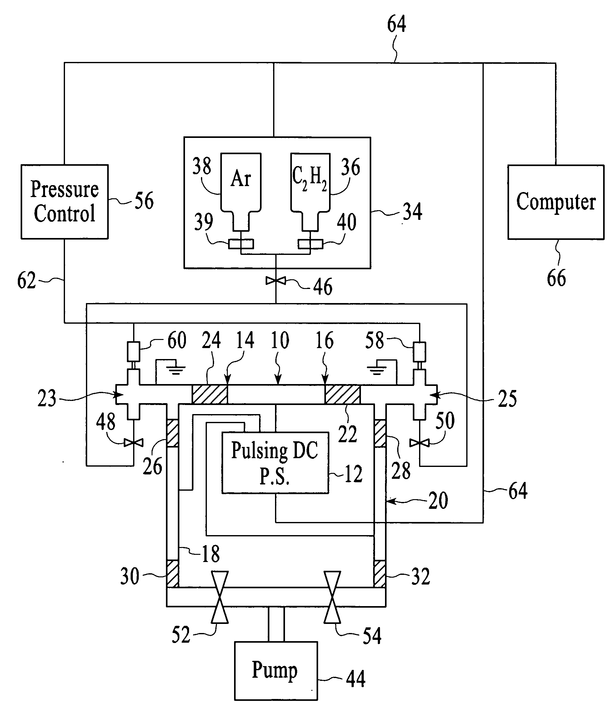
[0060]For the case of coating the interior of a 1.75 inch (44.45 millimeter) diameter by 12 inch (304.8 millimeters) long carbon steel (1222) pipe, using a DC pulse power supply to generate the plasma as described above. It should be noted that the power settings below are DC values and the per pulse power will be much higher, resulting in high ion bombardment as described earlier.[0061]A) The pipe is pumped to the low millitorr pressure range.[0062]B) The surface is activated and cleaned by introducing argon gas, and generating a plasma by applying a DC pulsed bias voltage.[0063]C) A nitrogen plasma is used to heat the part to the desired temperature.[0064]D) Adhesion PEB steps:[0065]1. Tetramethylgermanium precursor is introduced with argon at a pressure of 150 mTorr and a power of 180 watts with a 5% total duty cycle for 5 seconds.[0066]2. Argon is introduced for 4 minutes at a pressure of 65 mTorr with a power of 240 watts with a duty cycle of 15%.[0067]3. Steps A and B are repe...

example 2

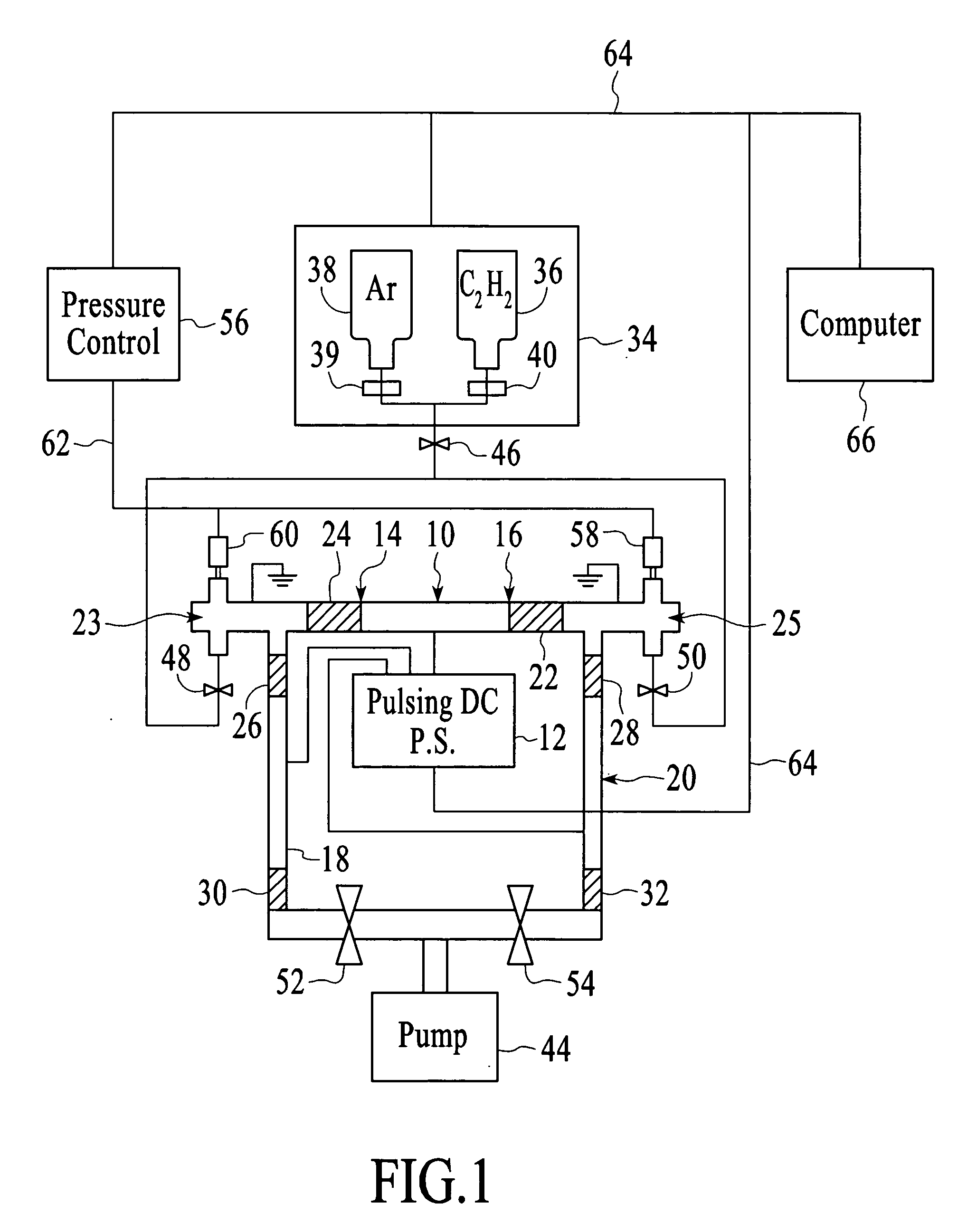
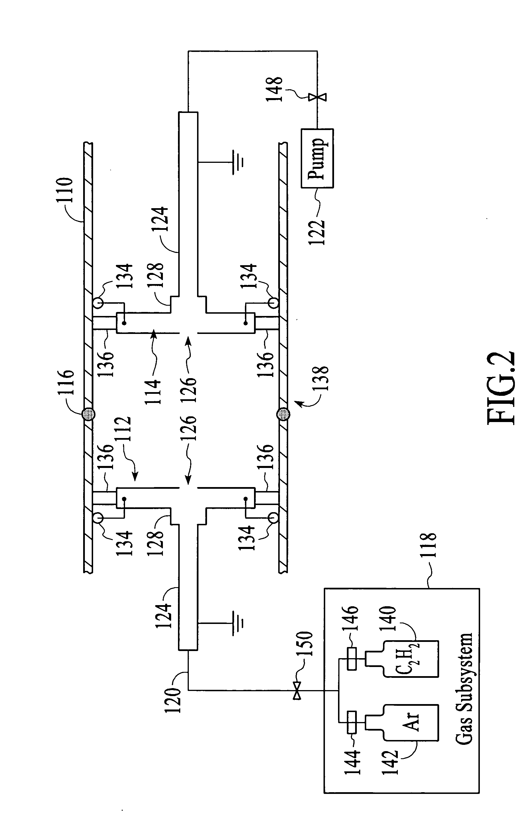
[0078]Deposition of a well bonded DLC layer to the interior of a 1.5 inch (38.1 millimeters) diameter by 6 inch (152.4 millimeters) long silicon carbide pipe. Good adhesion to a silicon carbide substrate is difficult to achieve, due to the strongly bonded ceramic structure of the substrate and thus the lack of dangling bonds available for bonding with the adhesion layer at the interface. An additional problem is the more insulating nature of the ceramic structure which resulted in high voltages, and severe arcing, when a conventional SiH4 deposited adhesion layer was used. In contrast with the PEB adhesion process the plasma ran at ˜20% lower voltage and 30% higher current with no arcing. Again, a DC pulse power source is used to generate the plasma.[0079]A) The pipe is pumped to the low millitorr pressure range.[0080]B) A nitrogen plasma is used to prepare the surface and to heat the part to the desired temperature.[0081]C) Adhesion PEB steps:[0082]2% SiH4 balance argon; is introdu...


PUM

PropertyMeasurementUnit
thicknessaaaaaaaaaa
thicknessaaaaaaaaaa
thicknessaaaaaaaaaa

Abstract

Plasma Enhanced Bonding (PEB) during a coating process is used to improve both adhesion and corrosion resistance of the resulting coating. New interfacial compounds may be formed, offering the increased resistance to corrosion, as well as enhanced bonding to the workpiece being coated and any subsequently formed layer, such as diamond-like carbon. In one embodiment, the PEB processing is employed during coating of at least one interior surface of the workpiece, which may be a pipe. In a first step, a thin film is deposited. Then, the film is exposed to a high energy etch-back plasma. This two-step cycle of depositing a film and then providing bombardment of the film may be repeated a number of times. Typically, the deposition step of the cycle is much shorter than the bombardment step.

Description

CROSS REFERENCE TO RELATED APPLICATION[0001]This application claims priority from co-pending provisional application No. 60 / 959,360, filed Jul. 13, 2007.TECHNICAL FIELD[0002]The invention relates generally to chemical vapor deposition systems and more specifically to methods and systems for promoting adhesion and corrosion resistance for a coating process.BACKGROUND ART[0003]The corrosion of industrial piping and other components such as valves and pumps is a major problem in some industries. The oil industry, in particular, faces severely corrosive environments, with corrosive gases and liquids such as H2S (hydrogen sulfide) at elevated temperatures and pressures. Additionally, these conditions form severe wear and erosion environments. One solution to these issues is to coat a lower grade base material with a high quality coating material having the desired high corrosion and wear-resistant properties. Typically, these types of properties will be found in metal, ceramic and partic...

Claims


Application Information

Patent Timeline
Patent Type & Authority Applications(United States)
IPC IPC(8): H05H1/24H05H1/00
CPCC23C16/0272C23C16/515C23C16/26C23C16/045
Inventor DORNFEST, CHARLES N.UPADHYAYA, DEEPAKBOARDMAN, WILLIAM JOHNBOINAPALLY, KARTHIK
Owner AGM CONTAINER CONTROLS
Why Eureka
Try Eureka