
Boring machine having differential global positioning system receiver for underwater rock and boring method thereof

a global positioning system and underwater rock technology, applied in special purpose vessels, drilling/well accessories, sealing/packing, etc., can solve the problems of swaying the barge 20 30 cm, and affecting the work efficiency of the boring machin

Inactive Publication Date: 2005-06-09
BAEK IN SUK +2
View PDF8 Cites 14 Cited by
  • Summary
  • Abstract
  • Description
  • Claims
  • Application Information

AI Technical Summary

Benefits of technology

[0019] It is an object of the present invention to provide a boring machine having a differential global positioning system receiver for underwater rock and boring method thereof, in which technology of DGPS is brought to the boring technology, and a boring machine that is installed at the central opening of the barge is concentric to the target underwater rock so that accurate boring can be attained.
[0020] It is another object of the present invention to provide a boring machine having a differential global positioning system receiver for underwater rock and boring method thereof, in which the position movement of the boring work can be done quickly without movement of the boring machine as well as without a troublesome knock down of the parts, thus enhancing the efficiency of the construction.
[0021] It is another object of the present invention to provide a boring machine having a differential global positioning system receiver for underwater rock and boring method thereof, in which the boring machine is provided at the center of the barge without direct influence from waves or other exterior forces, and making connection of the rod to be easy, and enabling the boring work having a large diameter executed, and so achieving the blasting and crushing work for underwater rock efficiently.
[0022] It is another object of the present invention to provide a boring machine having a differential global positioning system receiver for underwater rock and boring method thereof, in which the breakage of the boring machine rod can be prevented despite the swaying of the hull, thus proceeding with the work continuously.
[0043] Further, it has another characteristic in that the hull location control step and the hull movement step are the following steps: the winch driver operates under command of the controller; plural wire ropes wound on each winch are connected to respective anchors through the direction switch guider; the wire rope installed to move in a predetermined direction is wound and the wire rope installed to move in the opposite direction is released, thus achieving the movement of the hull.

Problems solved by technology

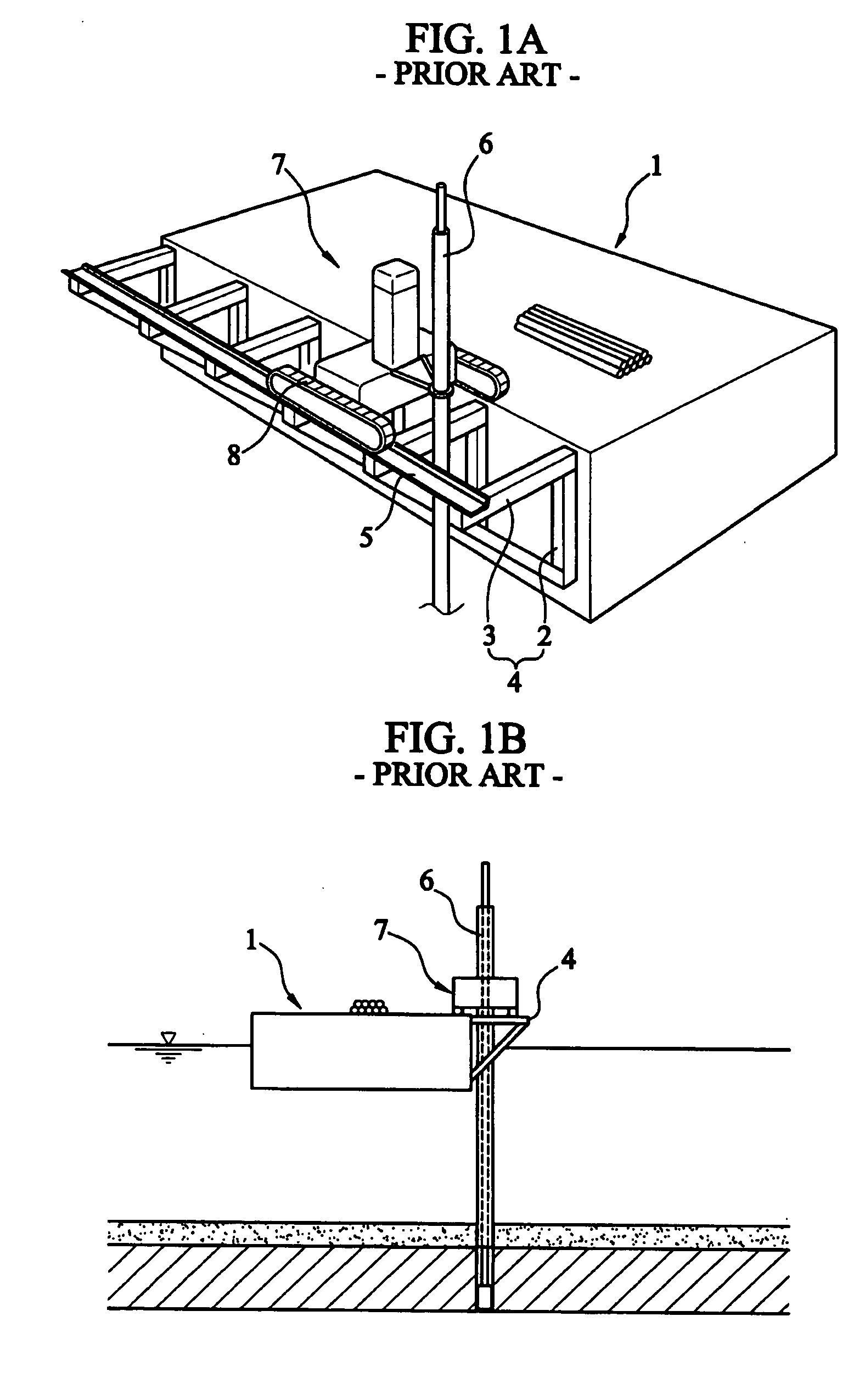
However, in the boring work of the sea, a barge is swayed 20˜30 cm owing to waves.
The rod can be broken, which causes a problem with the boring work.
Further, since the crawler drill is located at the side boarder of the platform offset from the center of the barge, there is a potential problem of instability because the rods installed the crawler drill can fall into the underwater.
It is attended with difficulties in the boring work.
It normally takes more than 30 minutes to move the next boring position, thus bringing the problem of inefficiency caused by the slow process of the boring work.
There is a limitation in increasing the diameter of the rod.
As the blasting hole having a small diameter (e.g. 75 mm) is dug, the position of the digging is inaccurate.
And also, since the small diameter of the boring hole has the increased volume of charge, it has the disadvantage that not much blast effect can be obtained.
Furthermore, if the prior art is adopted where a silt of the underwater covers the underwater rock, the silt around the blast hole having the small diameter or the rock debris go into the blast hole, which makes the charge loading difficult.
Otherwise, the charge must stick on the outer surface of the rock, which is inconvenient.

Method used


Image

  • Boring machine having differential global positioning system receiver for underwater rock and boring method thereof
  • Boring machine having differential global positioning system receiver for underwater rock and boring method thereof
  • Boring machine having differential global positioning system receiver for underwater rock and boring method thereof

Examples


Embodiment Construction

[0056] Reference should now be made to the drawings, in which the same reference numerals are used throughout the different drawings to designate same or similar components.

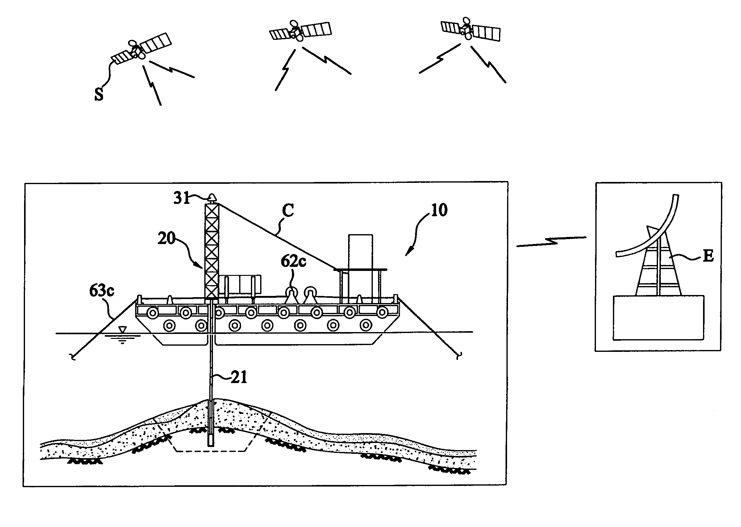
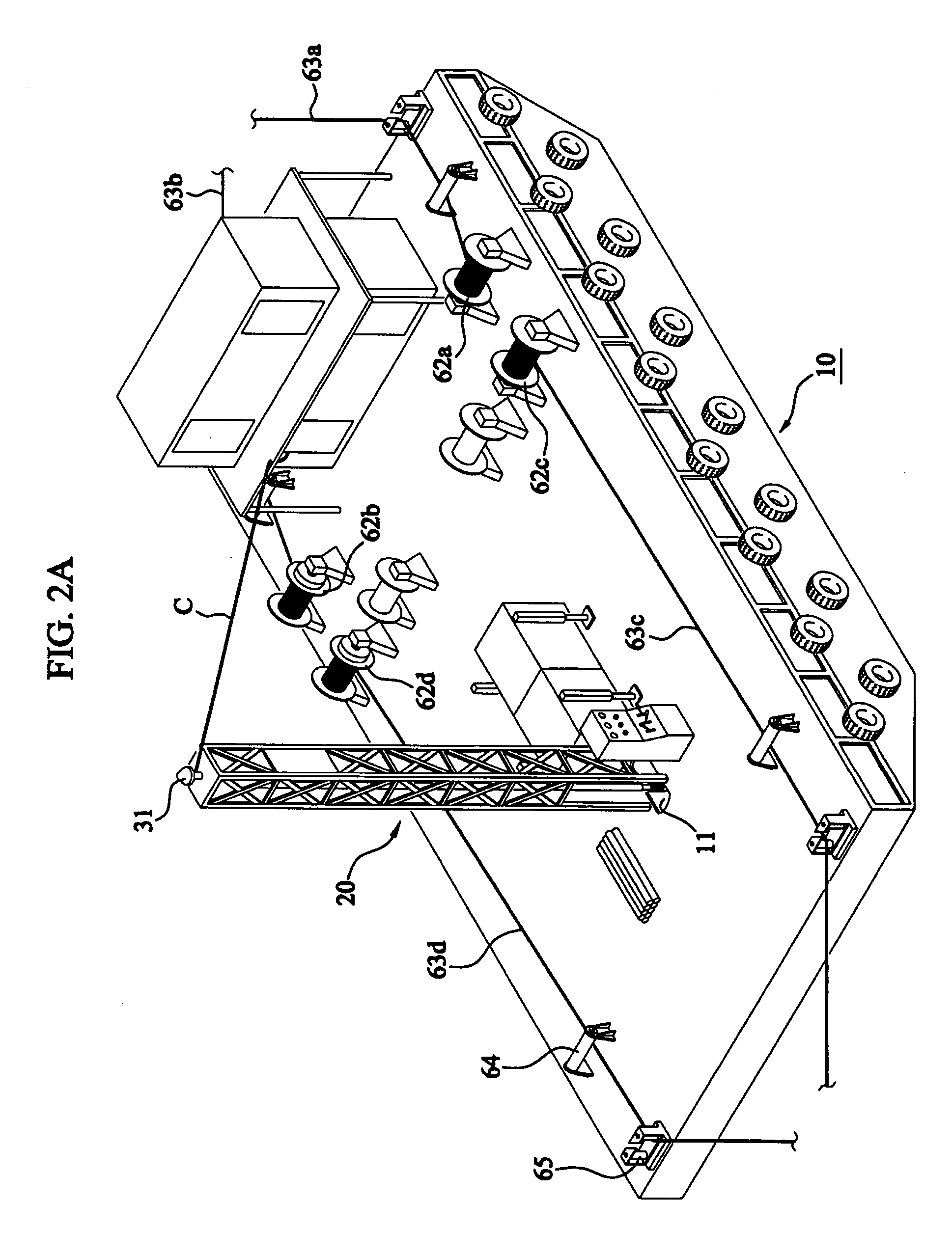
[0057]FIG. 2a is a perspective view of a barge that carries a boring machine having a differential global positioning system (DGPS) receiver for an underwater rock according to the present invention, and FIG. 2b is a side cross-sectional view illustrating that the barge stops at the sea to be bored and performs the boring work.

[0058] As shown in FIGS. 2a and 2b, a barge 10 has plural winches 62a, 62b, 62c, 62d installed on the barge 10, and respective wire ropes 63a, 63b, 63c, 63d are wound on respective winches 62a, 62b, 62c, 62d. The anchors (not shown) connected to plural wire ropes 63a, 63b, 63c, 63d are dropped on the underwater rock distanced at a predetermined length from each corner of the barge 10 so as to moor the barge 10.

[0059] The barge has an opening 11 with a predetermined size at the center of ...


PUM


Abstract

The present invention relates to a boring machine having differential global positioning system receiver for underwater rock and boring method thereof, new boring technology—a satellite navigation device orients the accurate position of a target—is brought to the underwater boring technology. A differential global positioning system (DGPS) receiver is provided at the body of a boring machine that is installed at the central opening of a self elevation platform (SEP) barge, the location of the boring machine is set to concentricity of the target boring position, and the position of the hull can be controlled without any movement of the boring machine. Then, the barge quickly moves to the next target boring location owing to the operation of a hull moving means so that the construction efficiency of the boring work can be enhanced.

Description

BACKGROUND OF THE INVENTION [0001] 1. Field of the Invention [0002] The present invention relates to a boring machine having differential global positioning system receiver for underwater rock and boring method thereof, and particularly the former in which a differential global positioning system (DGPS) receiver is provided at the body of a boring machine that is installed at the central opening of a self elevation platform (SEP) barge; a location data of the boring machine is received from a satellite and a reference station to bore in the underwater rock at an accurate boring location; and the barge quickly moves to the boring location so that the construction efficiency of the boring work can be enhanced. [0003] 2. Description of the Prior Art [0004] In examples, such as a pier groundwork for an underwater bridge structure, a sea structure construction for specific purpose, a development of a waterway for a large ship, and a berth construction for a large ship, the rock existed a...

Claims


Application Information

Patent Timeline
Patent Type & Authority Applications(United States)
IPC IPC(8): E21B7/128E21C37/00E21B41/00
CPCE21B7/128B63B2213/02B63B35/4413E21B41/0014E21C37/00
Inventor BAEK, IN SUKKIM, JONG SEOLKANG, DAE WOO
Owner BAEK IN SUK
Learn More