Method and apparatus for controlling the bandwidth frequency of an analog filter

Inactive Publication Date: 2005-06-09
NORTH STAR INNOVATIONS
View PDF6 Cites 47 Cited by
  • Summary
  • Abstract
  • Description
  • Claims
  • Application Information

AI Technical Summary

Problems solved by technology

However, bandwidth variations in an analog filter may lead to significant performance degradation in both the receive and transmit signal paths of the wireless device.
In the receive path, variations in the bandwidth of the receiver's baseband analog filter leads to performance degradation in static sensitivity, sensitivity in the presence of interferers, receiver IP3, and anti-aliasing performance.
Alternately, in the transmit pa

Method used


Image

  • Method and apparatus for controlling the bandwidth frequency of an analog filter
  • Method and apparatus for controlling the bandwidth frequency of an analog filter
  • Method and apparatus for controlling the bandwidth frequency of an analog filter

Examples


Example

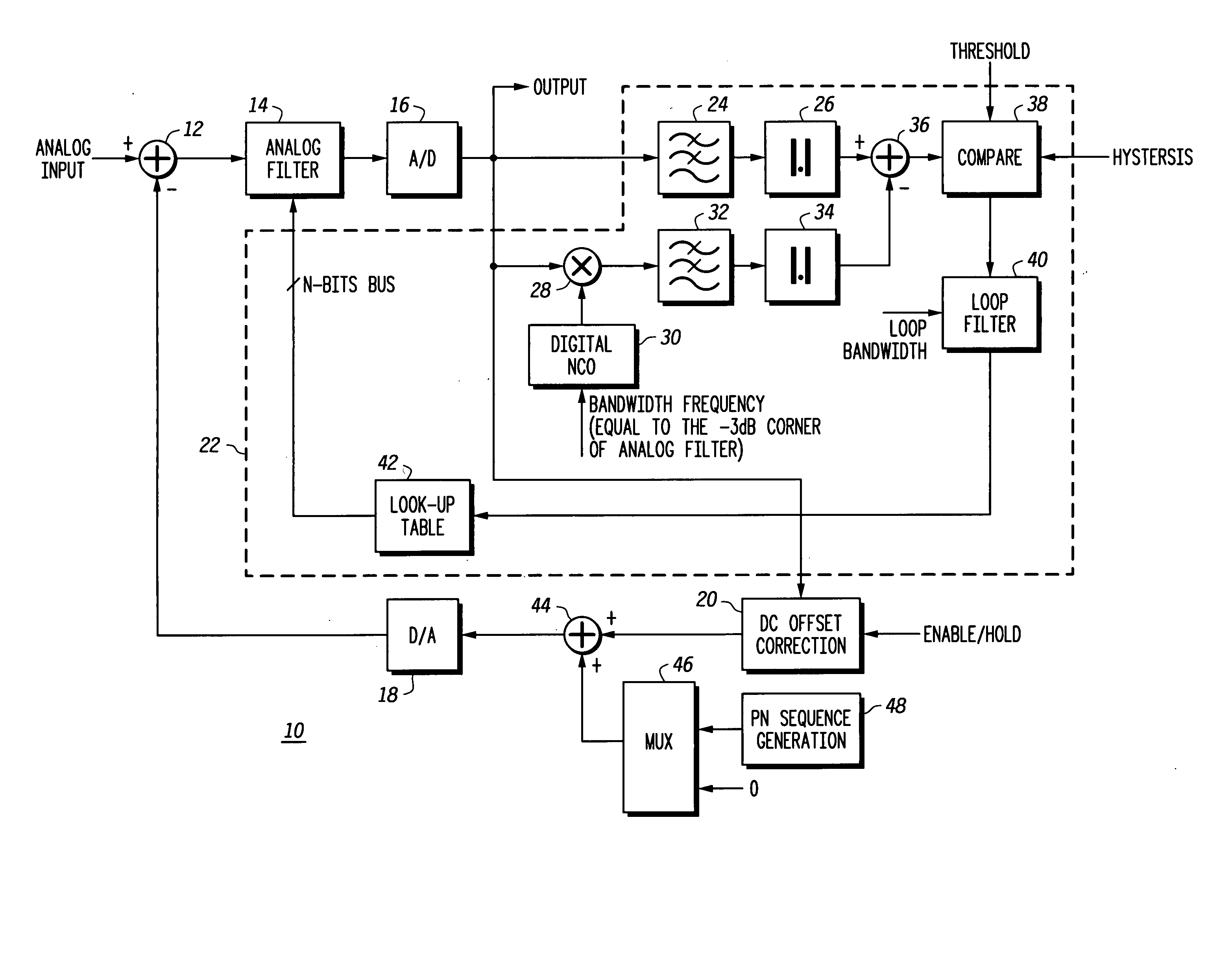
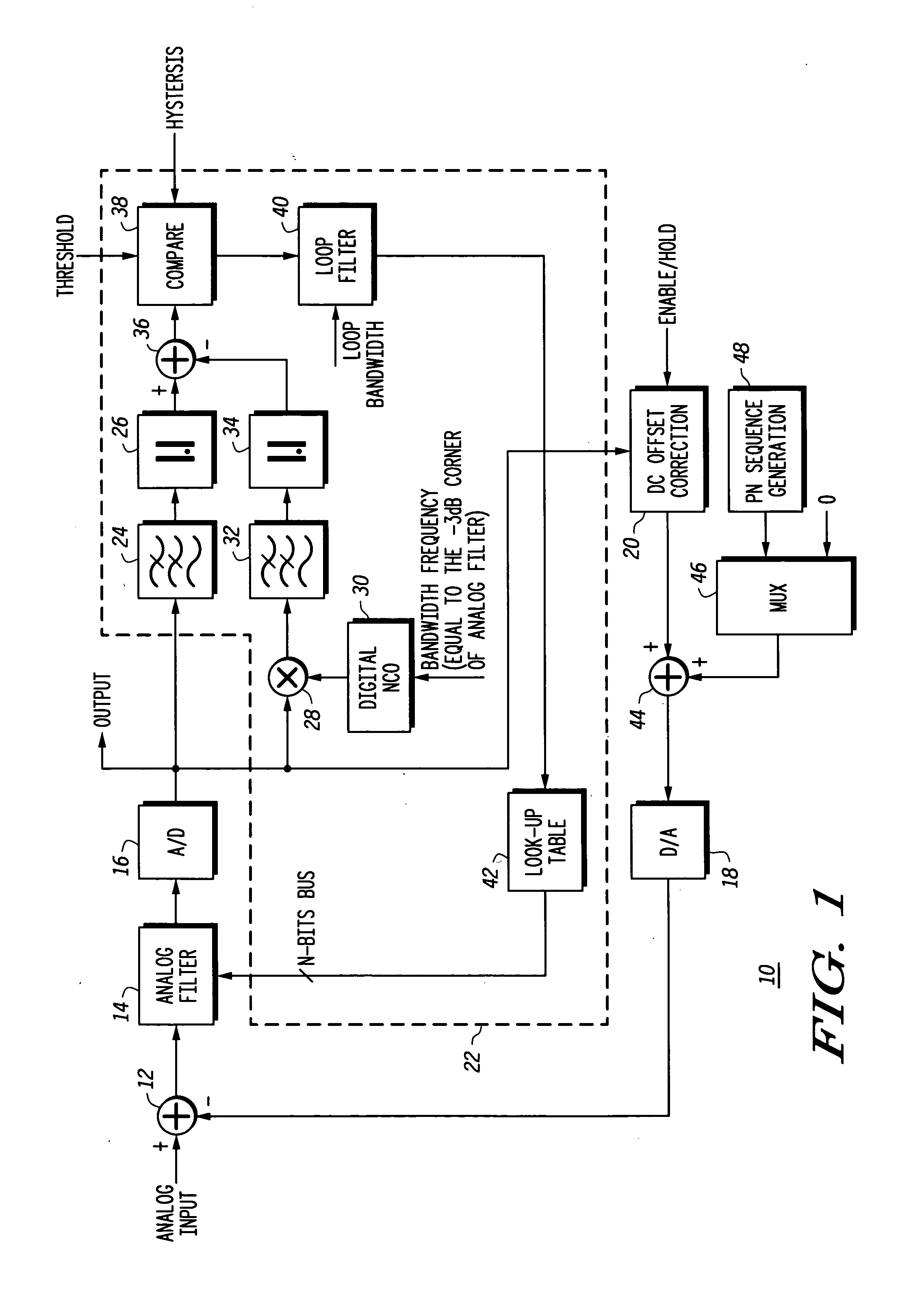
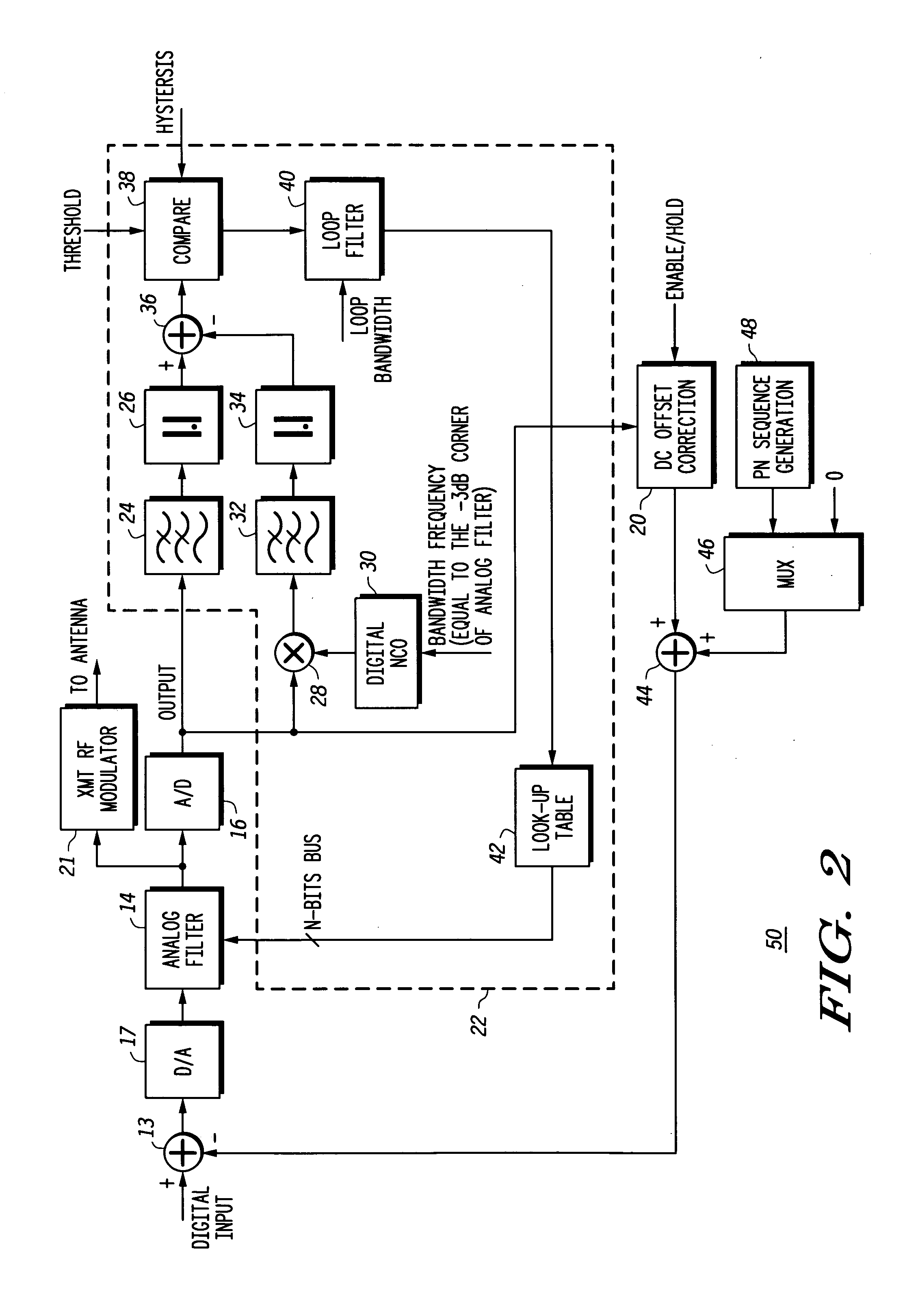
[0012] Generally, the present invention provides a higher performance, lower cost, and lower power digital approach to achieving bandwidth tracking of an analog filter without the need for achieving any matching between the analog filter and the tracking circuit itself. The analog filter bandwidth tracking loop includes an analog filter element (either active or passive), and a digital tracking loop. This analog filter may be a lowpass, bandpass, or highpass filter. The digital tracking loop compares a magnitude difference to a predetermined threshold to generate an error signal. The magnitude difference is determined during a closed loop bandwidth calibration process by subtracting a magnitude of an analog input signal over a predetermined frequency range near the center frequency of the analog filter to a magnitude of the analog input signal over a predetermined frequency range near the bandwidth frequency of the analog filter. The result of this subtraction is then compared to a ...


PUM


Abstract

An analog filter (10) having a bandwidth tracking circuit includes an analog filter element (14) and a digital tracking loop (22). The digital tracking loop (22) compares a magnitude difference to a predetermined threshold to generate an error signal. The magnitude difference is determined during a closed loop bandwidth calibration by subtracting a first magnitude of an analog input signal over a predetermined frequency range to a second magnitude of the analog input signal over the predetermined frequency range located near the bandwidth frequency. Use of the digital tracking loop (22) provides a digital approach for achieving bandwidth tracking of an analog filter without the need for achieving any manufacturing process matching between the analog filter and the tracking circuit itself. The analog filter element (14) may be either a lowpass, highpass, bandpass, active or passive filter element.

Description

REFERENCE TO RELATED COPENDING APPLICATION [0001] This application is related to U.S. patent application Ser. No. 10 / 096,460, entitled “SELF CALIBRATING TRANSMIT PATH CORRECTION SYSTEM” by Mahibur Rahman et al., filed Mar. 12, 2002, and assigned to the assignee hereof.FIELD OF THE INVENTION [0002] This invention relates to integrated circuits (ICs), and more particularly to a method and apparatus for controlling the bandwidth frequency of an analog filter. BACKGROUND OF THE INVENTION [0003] Analog filters are frequently used in wireless devices such as cellular telephones. However, bandwidth variations in an analog filter may lead to significant performance degradation in both the receive and transmit signal paths of the wireless device. In the receive path, variations in the bandwidth of the receiver's baseband analog filter leads to performance degradation in static sensitivity, sensitivity in the presence of interferers, receiver IP3, and anti-aliasing performance. For example, i...

Claims


Application Information

Patent Timeline
IPC IPC(8): H03H11/12H04B1/66H04B1/707
CPCH03H11/1291
Inventor RAHMAN, MAHIBURGUIMARAES, HOMERO LUZ
Owner NORTH STAR INNOVATIONS
Why Eureka
Try Eureka