Catalyzed hydrogen desorption in Mg-based hydrogen storage material and methods for production thereof

Inactive Publication Date: 2005-06-16
TEXACO OVONIC HYDROGEN SYST LLC
View PDF6 Cites 22 Cited by
  • Summary
  • Abstract
  • Description
  • Claims
  • Application Information

AI Technical Summary

Benefits of technology

[0058] The catalyst may be distributed in multiple ways by combining the above techniques. The bulk or particulate magnesium or magnesium-based hydrogen storage alloy may be produced by; a) forming a melt of said magnesium or magnesium-based hydrogen s

Problems solved by technology
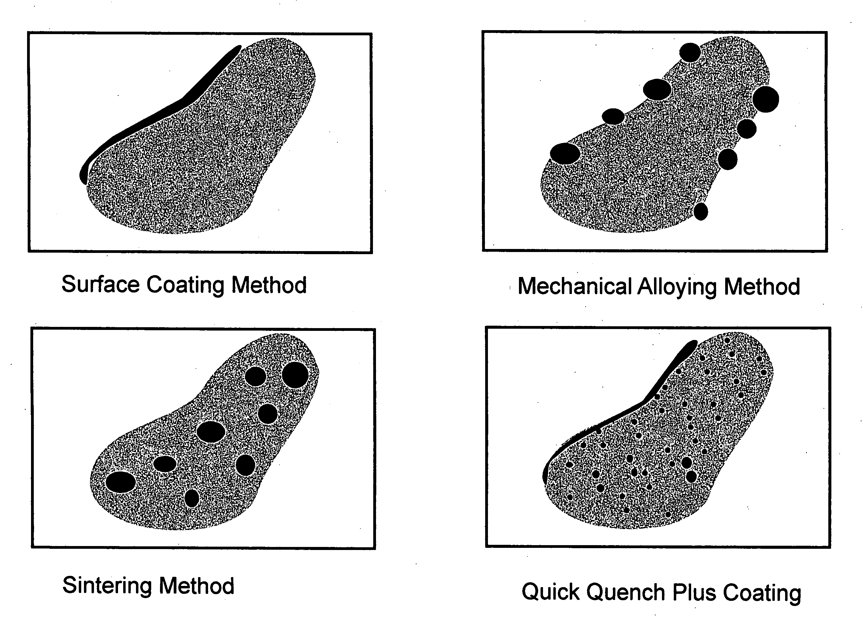
One of the problems posed by the use of hydrogen is its storage and transportation.
Hydrogen may be stored under high pressure in steel cylinders, but this approach has the drawback of requiring hazardous and heavy containers which are difficult to handle (in addition to having a low storage capacity of about 1% by weight).
Hydrogen may also be stored in cryogenic containers, but this entails the disadvantages associated with the use of cryogenic liquids; such as, for example, the high cost of the containers, which also require careful handling.
Although this property and the relatively low price of magnesium make the MgH2—Mg seem the optimum hydrogen storage system for transportation, for hydrogen-powered vehicles that is, its unsatisfactory kinetics have prevented it from being used up to the present time.
Moreover, the hydrogen storage capacity of a magnesium reserve diminishes during the charging/discharging cycles.
The high temperature level and the high energy requirement for expelling the hydrogen have the effect that, for example, a motor vehicle with an internal combustion engine, cannot exclusively be operated from these alloys.
For example, this alloy can be titanium/iron hydride (a typical low-temperature hydride store) which can be operated at temperatures down to below 0° C. These low-temperature hydride alloys have the disadvantage of having a low hydrogen storage capacity.
In addition to this relatively low storage capacity, these alloys also have the disadvantage that the price of the alloy is very high when metallic vanadium is used.
Although alloys of this type have a greater storage capacity for hydrogen than the alloy according to U.S. Pat. No. 4,160,014, hereby incorporated by reference, they have the disadvantage that temperatures of at least 250° C. are necessary in order to completely expel the hydrogen.
However, a high discharge capacity, particularly at low temperatures, is frequently necessary in industry because the heat required for liberating the hydrogen from the hyd

Method used


Image

  • Catalyzed hydrogen desorption in Mg-based hydrogen storage material and methods for production thereof
  • Catalyzed hydrogen desorption in Mg-based hydrogen storage material and methods for production thereof
  • Catalyzed hydrogen desorption in Mg-based hydrogen storage material and methods for production thereof

Examples


example 1

[0076] Raw materials consisting of pure metal powders of magnesium (99.8%, −325 mesh), aluminum (99.5%, −325 mesh), iron (99.9+%, 10 micron) and other minor constituents were mixed in an agate mortar-pestle. Ten different compositions were produced, and their compositions in weight percent are listed in Table 1. A hardened steel die was used to press the mixed powders into a pellet of 1 cm diameter and 1 cm long. The pressed pellet was placed in a quartz tube and was sintered at a temperature above 500° C. for 22 hours under vacuum.

TABLE IChemical composition (all numbers are in weight percentage)Alloy NumberMgAlFeBCuPdVNiCScMM-188.82.78.5———————MM-287391——————MM-386392—————MM-48639—2—————MM-58736—4—————MM-68738——2————MM-78738———2———MM-887—9————4——MM-987—9—————4—MM-108737——————3

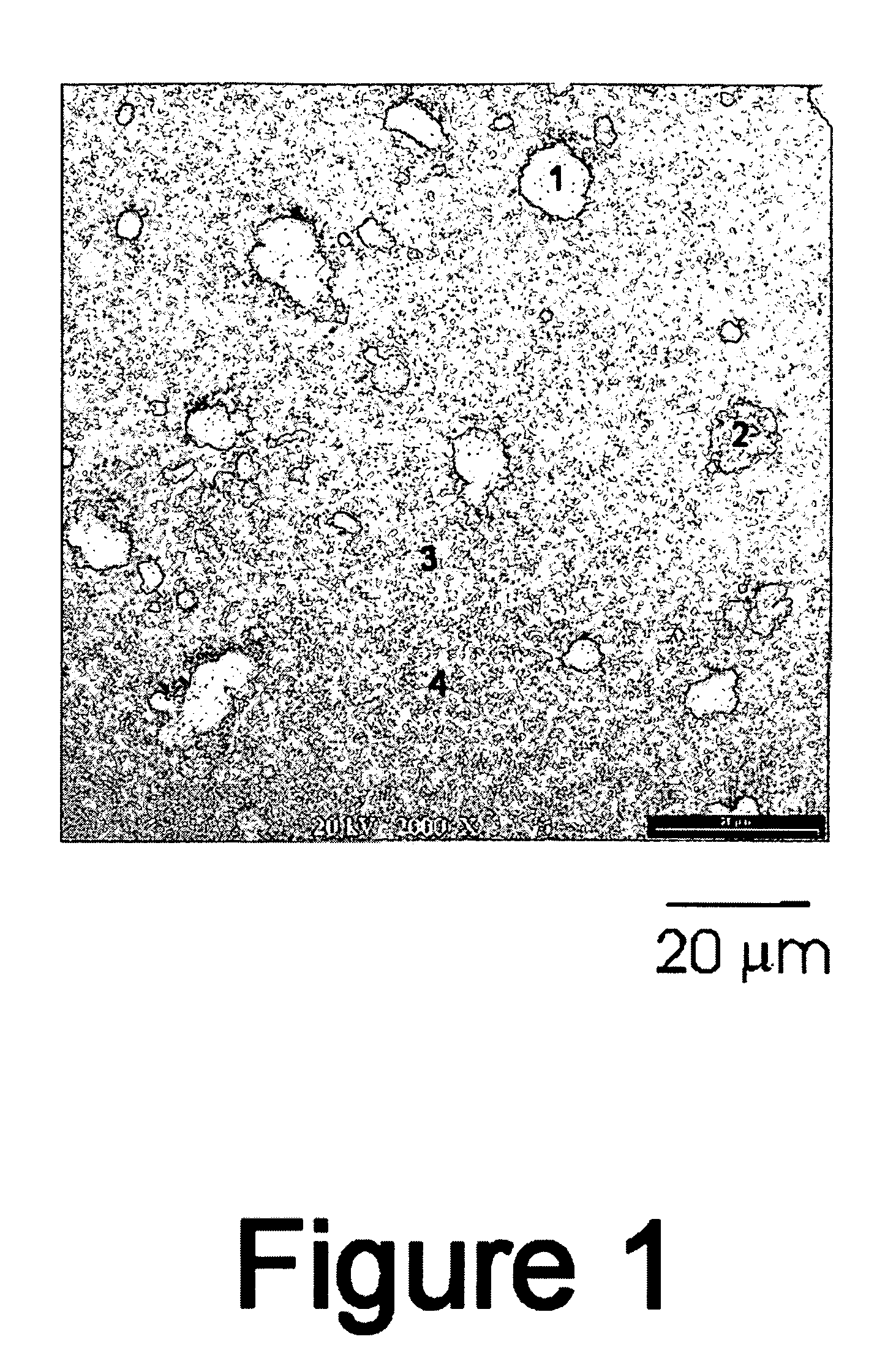
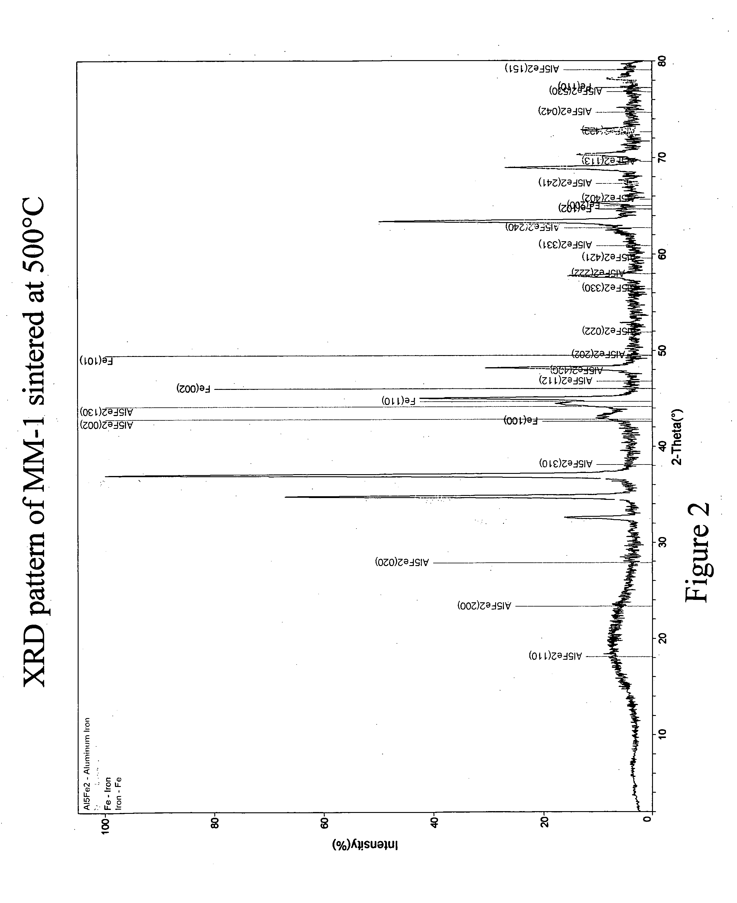
[0077]FIG. 1 is a scanning electron micrograph (SEM) taken in back-scattering mode of an MM-1 sample sintered / annealed at 500° C. The SEM indicates phase segregation of Fe and an Al5Fe2 intermetallic compou...

example 2

[0079] Another MM-1 material was produced by the process described in Example 1 with a change in sintering / annealing temperature. FIG. 6 plots the PCT curves of samples sintered / annealed at 570° C. and 600° C. respectively. While the PCT of the material sintered / annealed at 570° C. shows little deviation from that of the material of Example 1 (which was sintered / annealed at 500° C.), the material sintered / annealed at 600° C. provides an extended plateau at a slightly higher pressure.

example 3

[0080] The mechanically alloyed (MA) powders of MM-1 were prepared from mixtures of pure elemental magnesium (99.8%, −325 mesh), aluminum (99.5%, −325 mesh), and iron (99.9+%, 10 micron). The milling was carried out in an attritor loaded with Cr-steel grinding balls. The mechanical alloying process is performed under an argon atmosphere with the addition of 1% graphite and heptane to keep material from caking on the attritor walls. Typical milling time is two hours. FIG. 7 is an SEM back-scattering micrograph of this sample. The figure indicates severe phase segregation within the material. Region 1 (bright contrast on the picture) is filled with Fe and Al powder while Region 2 (central darker area) is all magnesium. FIG. 8, which is the XRD plot of the sample, shows no indication of any amorphous intermetallic product formed by this process. The MA-MM-1 powder was pressed onto an expanded nickel metal substrate and then coated on both sides with 100 angstroms of iron as surface cat...


PUM

PropertyMeasurementUnit
Temperatureaaaaaaaaaa
Timeaaaaaaaaaa

Abstract

A magnesium-based hydrogen storage material including magnesium or a magnesium-based hydrogen storage alloy and a hydrogen desorption catalyst which is insoluble in said magnesium-based hydrogen storage alloy and is in the form of: 1) discrete dispersed regions of catalytic material in the bulk of said magnesium or magnesium-based hydrogen storage alloy; 2) discrete dispersed regions on the surface of particles of said magnesium or magnesium-based hydrogen storage alloy; 3) a continuous or semi-continuous layer of catalytic material on the surface of said magnesium or magnesium-based hydrogen storage alloy which is in bulk or particulate form; or 4) combinations thereof. Methods of producing the material are also disclosed.

Description

FILED OF THE INVENTION [0001] The instant invention relates generally to hydrogen storage materials and more specifically magnesium-based hydrogen storage materials in which hydrogen desorption is catalyzed by materials which are insoluble in said magnesium-based hydrogen storage material. The insoluble catalytic material may be in the form of: 1) discrete dispersed regions of catalytic material in a hydrogen storage material bulk; 2) discrete dispersed regions on the surface of particles of the hydrogen storage material; 3) a continuous or semi-continuous layer of catalytic material on the surface of bulk or particulate hydrogen storage material; or 4) combinations thereof. BACKGROUND OF THE INVENTION [0002] Growing energy needs have prompted specialists to take cognizance of the fact that the traditional energy resources, such as coal, petroleum or natural gas, are not inexhaustible, or at least that they are becoming costlier all the time, and that it is advisable to consider rep...

Claims


Application Information

Patent Timeline
IPC IPC(8): C22C23/00
CPCB01J23/745B01J37/0244Y02E60/327C22C2202/04C22C1/0408C01B3/0078C01B3/0031C01B3/0026B22F2998/10C22C1/1084B22F3/02B22F3/10B22F9/04Y02E60/32C22C23/00
Inventor FETCENKO, MICHAEL A.YOUNG, KWOTUNG, CHENGOVSHINKSY, STANFORD R.
Owner TEXACO OVONIC HYDROGEN SYST LLC
Why Eureka
Try Eureka