Plastic optical components

a technology of optical components and plastics, applied in the field of optical components, can solve problems such as the change in the optical performance of plastic lenses, and achieve the effects of improving the optical performance of plastic lenses

Active Publication Date: 2005-06-16
FUJIFILM CORP +1
View PDF2 Cites 7 Cited by
  • Summary
  • Abstract
  • Description
  • Claims
  • Application Information

AI Technical Summary

Benefits of technology

[0018] According to the present invention, there is offered the advantage of easily realizing and providing plastic optical components which retain the superior characteristics of plastic optical components themselves such as lightweightness, low cost and suit

Problems solved by technology

As a result, they found that the changes in the optical performance of plastic lenses due to moisture absorption were mainly attributable to the unevenness in refractiv

Method used


Image

  • Plastic optical components
  • Plastic optical components
  • Plastic optical components

Examples


example 1

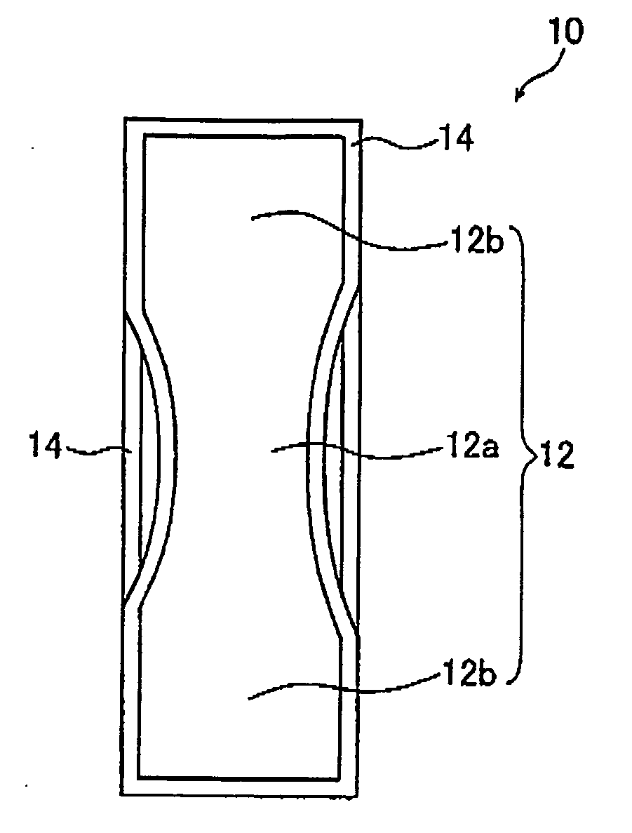
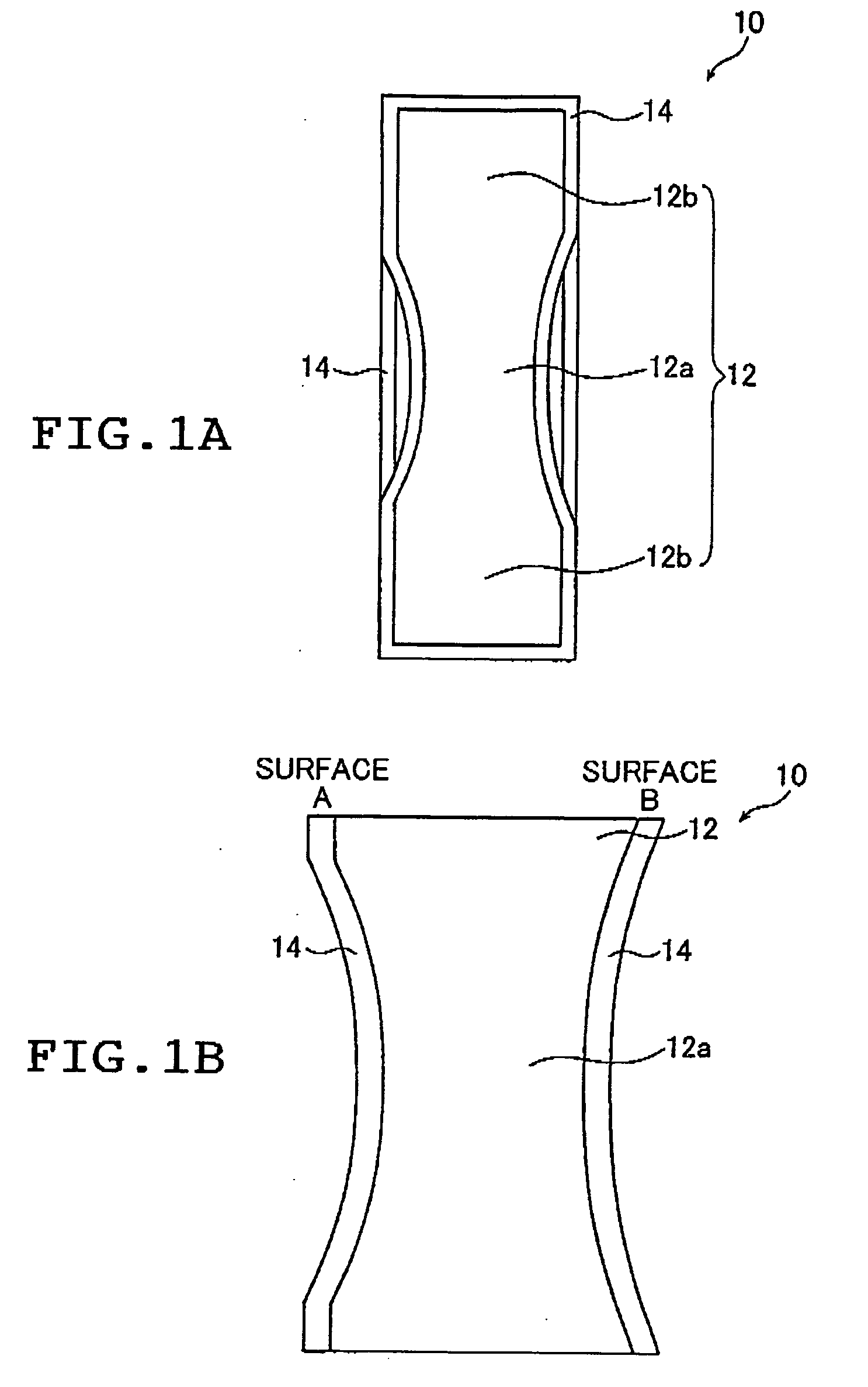
[0083] A polycarbonate lens having the above-described shape and size was prepared as the main body 12 of an optical component by injection molding.

[0084] By sputtering, a moisture-proof coating 14 made of Si and O was deposited in a thickness of about 100 nm on all surfaces of the main body 12 to fabricate the optical component 10 of the present invention. The sputter target was a silicon plate. During sputtering, Ar was introduced at the time the pressure reached 7×10⁻⁴ Pa and electric discharge was performed at 0.3 Pa for 5 minutes to effect plasma treatment on the lens surfaces of the main body 12. Subsequently, the Si target was pre-sputtered for 3 minutes. Thereafter, the discharge power was increased 4-fold and with O2 being introduced as a reactive gas, the main body 12 which was the polycarbonate lens was subjected to deposition treatment at 0.3 Pa until a clear moisture-proof coating 14 formed in a thickness of 100 nm.

[0085] The thus obtained optical component 10 of Exam...

example 2

[0086] A polycarbonate lens was fabricated as in Example 1 to make the main body 12. To all surfaces of this main body 12, an undercoating agent (WS-5000; product of Mitsui Takeda Chemicals, Inc.) was applied and dried at 80° C. for 30 minutes. Subsequently, a vinylidene chloride latex (L551B; product of ASAHI KASEI CORP.) was applied and dried at 110° C. for 30 minutes. Thereafter, the substrate was left to stand at 35° C. for 2 days until a clear moisture-proof coating 14 formed. The overall thickness of the moisture-proof coating 14 including the undercoat was 8 μm.

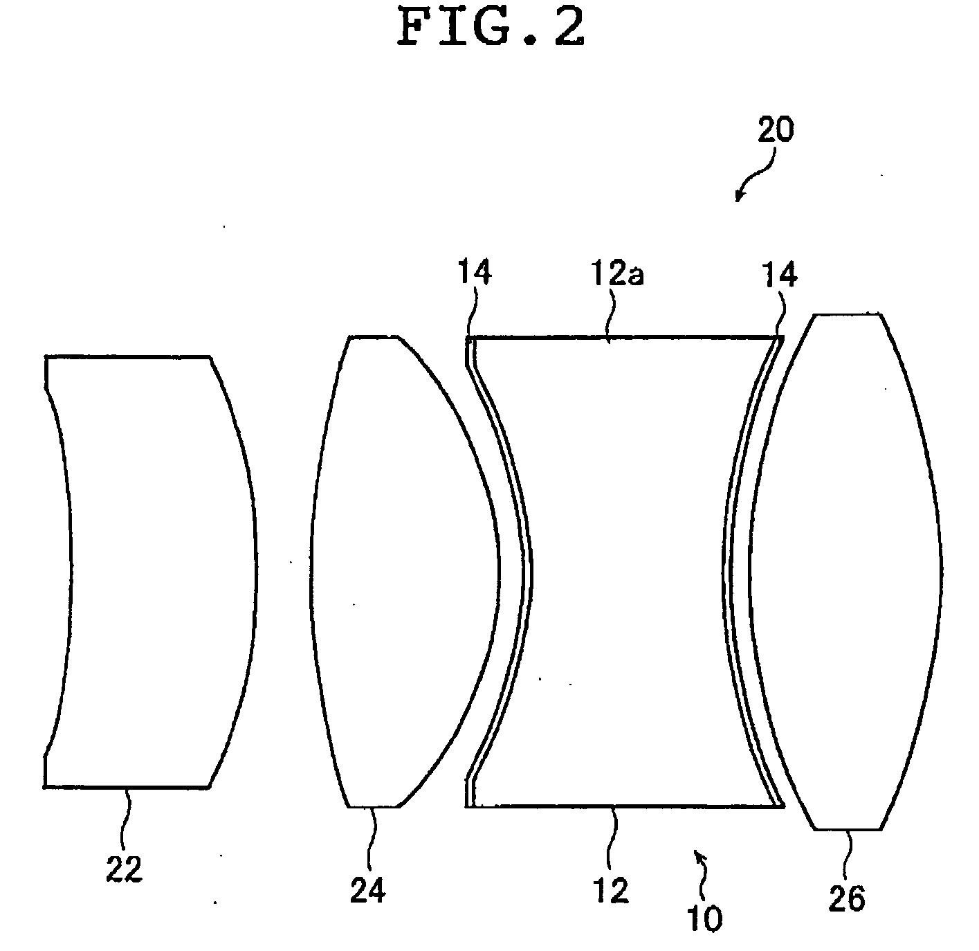
[0087] The thus obtained optical component 10 of Example 2 consisted of the main body 12 and the moisture-proof coating 14 and it was assembled into the lens unit 20.


PUM

PropertyMeasurementUnit
Transparencyaaaaaaaaaa

Abstract

The plastic optical component includes a main body and a transparent moisture-proof coating provided on all surfaces of the main body, the moisture-proof coating satisfying the following relation (1):
(D1/d)×(L/D2)<10   (1)
where D1 (mm2/s) is a water diffusion coefficient of a first material of which the moisture-proof coating is made, d (mm) is a thickness of the first material, D2 (mm2/s) is the water diffusion coefficient of a second material of which the main body is made, and L (mm) is an average thickness across an optical surfaces of the second material.

Description

[0001] This application claims priority on Japanese patent application No.2003-414685, the entire contents of which are hereby incorporated by reference. In addition, the entire contents of literatures cited in this specification are incorporated by reference. FIELD OF THE INVENTION [0002] This invention relates to the technical field of optical components such as lens and prism that are made of plastics, more particularly to plastic optical components that experience extremely small changes in optical performance due to moisture absorption. [0003] Conventionally, camera lenses and a variety of lenses used in finders, copy equipment, printers, projectors and optical communications, as well as optical components including prisms, spectacle lenses, contact lenses and magnifiers are mostly manufactured from glass. [0004] However, with the recent progress in plastic materials and in the plastics molding technology, it has become possible to manufacture lenses, prisms and other optical c...

Claims


Application Information

Patent Timeline
IPC IPC(8): G02B1/04G02B1/10
CPCG02B1/105G02B1/18
Inventor SUZUKI, FUMIYUKIEIHA, NORIKOMOCHIZUKI, TADASHIKIDO, TAKEO
Owner FUJIFILM CORP
Why Eureka
Try Eureka