Fuel cell system
- Summary
- Abstract
- Description
- Claims
- Application Information
AI Technical Summary
Benefits of technology
Problems solved by technology
Method used
Image


Examples
embodiment
Configuration of Embodiment
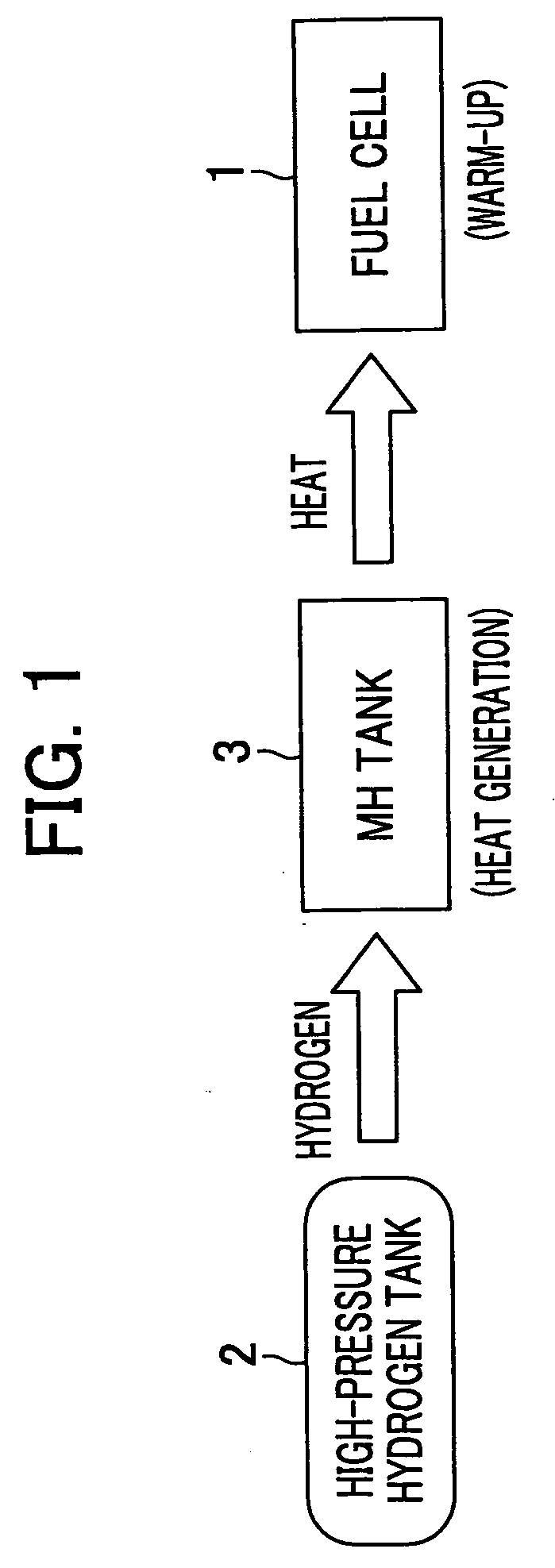
[0049] In the embodiment to be described below, electricity is generated by supplying the hydrogen to the fuel cell while the fuel cell is warmed up by the heat generated when the hydrogen is absorbed by the hydrogen storage alloy.
[0050] First, a vehicle will be explained. In the vehicle V shown in FIG. 4, a FC box FCB is mounted underneath the floor of a passenger's seat. In the FC box FCB, a fuel cell 10 (see FIG. 5) is stored. A travel motor M is mounted in the front part of the vehicle V. A high-pressure hydrogen tank 21 and an MH tank 31 are mounted in a horizontal state above the rear wheel of the vehicle V. The heat generated by the MH tank 31 warms up the fuel cell 10 using a cooling liquid flowing through a primary cooling system pipe of the fuel cell 10 (not shown) The fuel cell 10 is connected to the high-pressure hydrogen tank 21 and the MH tank 31 through a hydrogen supply line (not shown).
[0051] The fuel cell 10 is connected to an air comp...
PUM
 Abstract
Description
Claims
Application Information
 - Generate Ideas
- Intellectual Property
- Life Sciences
- Materials
- Tech Scout
- Unparalleled Data Quality
- Higher Quality Content
- 60% Fewer Hallucinations
Browse by: Latest US Patents, China's latest patents, Technical Efficacy Thesaurus, Application Domain, Technology Topic, Popular Technical Reports.
© 2025 PatSnap. All rights reserved.Legal|Privacy policy|Modern Slavery Act Transparency Statement|Sitemap|About US| Contact US: help@patsnap.com